



Contents: Check on the car ⤓ Unscrewing the telescopic stand nut…⤓ Recycling of telescopic stand ⤓ Installing the upper spring support…⤓ Installing a telescopic stand…⤓ Examination ⤓
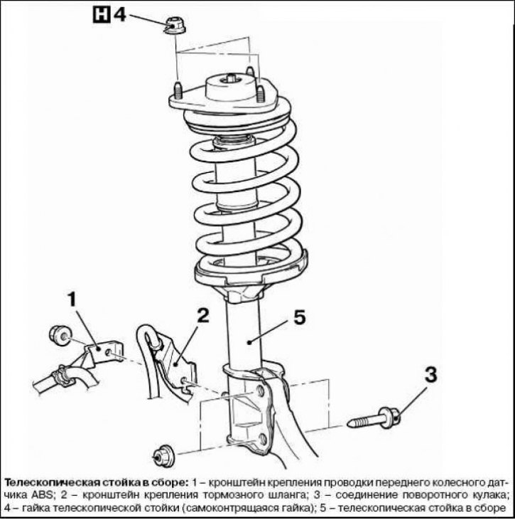
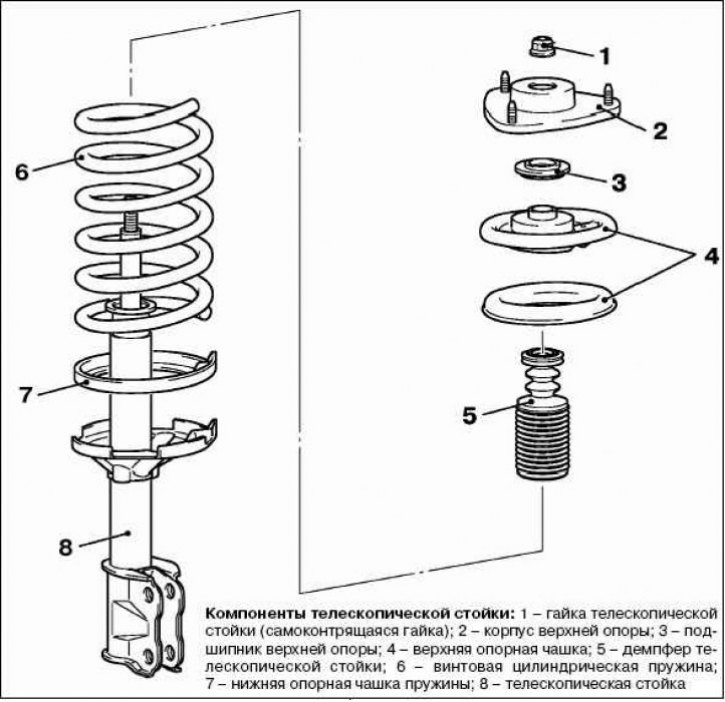
Check on the car
Check for leaks of working fluid from the telescopic strut. Check the condition of the telescopic strut for damage or deformation.
Unscrewing the telescopic stand nut (self-locking nut)
Caution! Install the special tool (MB991238) evenly so that its maximum length matches the length of the spring.
Warning! Do not use an impact wrench to compress the tool (MB991237): the special tool will break.
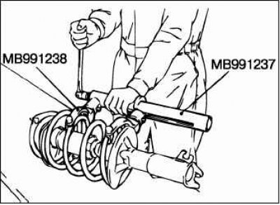
To compress the suspension spring, use the following special tool.
- MB991237: Spring compressor device.
- МВ991238: set of levers.
Warning! Do not use an impact wrench to loosen the telescopic strut nut (self-locking nut). The vibration from the impact wrench will cause the special tool (MB991237 and MB991238) to slip, resulting in injury.
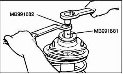
Use the following special tool to fix the telescopic stand, then the telescopic stand nut (self-locking nut) can be loosened.
- MB991681: key.
- MB991682: socket head (key).
Recycling of telescopic stand
Caution: Wear safety glasses to protect your eyes from flying metal chips.
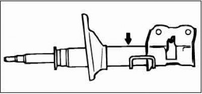
Before scrapping, the gas must be removed from the telescopic stand. Lay the telescopic stand horizontally and extend the stand rod. Drill a hole of about 3 mm in diameter in the place shown in the figure and release the gas from the stand.
Installing the upper spring support cup
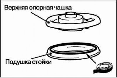
If the upper spring support cup has come away from the strut pad, connect the cup and pad using double-sided tape.
Installing a telescopic stand (self-locking nut)
Make sure the bearing is seated correctly.
Warning! Do not use an impact wrench to compress the tool (MB991237): the special tool will break.
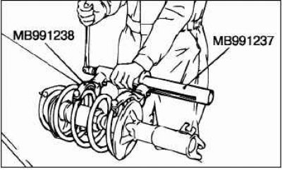
To compress the suspension spring, use the following special tool.
- MB991237: Spring compressor device.
- МВ991238: set of levers.
Since the spring is compressed by the special tool at this stage, temporarily tighten the strut nut (self-locking nut).
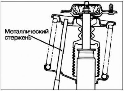
Align the hole in the lower support cup with the hole in the upper support cup.
Note: Use a rod to make this operation easier.
Align the lower end of the spring with the recess in the lower support cup, then remove the special tool.
Caution! It is not allowed to use an impact wrench to tighten the self-locking nut, otherwise the strut nut (self-locking nut) will be damaged.
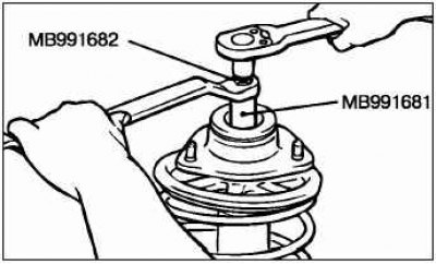
Using the following special tool, tighten the strut nut (self-locking nut) to a torque of 60 + 10 N·m.
Examination
Check the condition of the telescopic strut bearing for wear or corrosion.
Check the condition of the rubber parts for damage or destruction.
Check the condition of the suspension spring for deformation, damage or destruction.
Check the condition of the telescopic stand for deformations.