



Removal
To remove the lower arm, perform the following operations.
Use a ball joint puller to disconnect the lower control arm ball joint pin from the steering knuckle.
Attention! To prevent the puller from bouncing, it must first be tied with a cord or wire.
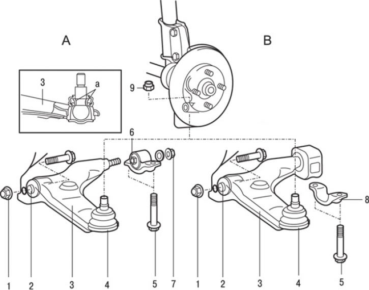
Fig. 15.30. Lower arm of the front suspension of models produced since 1995: a - places of lubrication application; A – cars with DOHC engines; B – cars with SOHC engines; 1* – nut (99–118 Nm); 2 – connection of the front bushing of the lower arm; 3 – lower arm assembly; 4 – lower arm ball joint connection; 5 – bolt (88 Nm); 6 – rear bushing of the lower arm of cars with DOHC engines; 7* – nut (137 Nm); 8 – support bracket for cars with SOHC engines; 9 – nut
1. Loosen the ball joint pin mounting nut, but do not unscrew it from the pin completely. Using a puller, remove the ball joint pin 4 (Fig. 15.30) from the front suspension strut.
Note: Parts marked with (*) in Fig. 15.30 must be pre-tightened and final tightening should be done after the vehicle has been lowered onto its wheels in an unloaded condition.
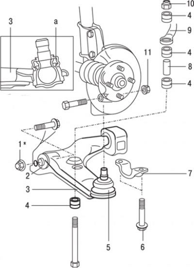
Fig. 15.31. Lower arm of the front suspension of models produced since 1999: a – place of application of lubricant; 1* – nut (88 Nm); 2 – connection of the front bushing of the lower arm; 3 – lower arm assembly; 4 – rubber bushing of the anti-roll bar; 5 – lower arm ball joint connection; 6 – bolt (88 Nm); 7 – support bracket; 8 – sleeve; 9 – anti-roll bar; 10 – self-locking nut; 11 – nut (88 Nm)
3. On vehicles produced since 1999, where the stabilizer is attached to the lower arm, unscrew the self-locking nut 10 (Fig. 15.31) and remove the rubber bushings 4 and sleeve 8.
4. On models with engines with two overhead camshafts (DOHC), unscrew the two bolts and disconnect the rear bushing 6 (see Fig. 15.30) of the lower arm.
5. On models with single overhead camshaft (SOHC) engines, remove the two bolts and disconnect the support bracket 8.
6. Remove the lower arm 3 as an assembly.
(The material was created based on the website: «MITSUBISHIMAN»)
Caution! Parts marked with an (*) in Fig. 15.31 must be pre-tightened and final tightening should be performed after the vehicle has been lowered onto its wheels in an unloaded state.
Examination
1. Check the rubber bushings for wear or damage.
2. Check the lower control arm for bending or cracks.
3. Check the support bracket for wear or damage.
4. Check the ball joint protective covers for cracks.
5. Check all bolts for bending or damage.
Installation
Installation is carried out in the reverse order of removal, taking into account the following.
1. On vehicles manufactured since 1999, tighten the self-locking nut so that the protrusion of the threaded portion of the stabilizer bar mounting bolt corresponds to the nominal value of 22 mm.
2. Adjust the front wheel alignment angles.