



Contents: Removal ⤓ Installation ⤓
Removal
1. Remove the cross beam.
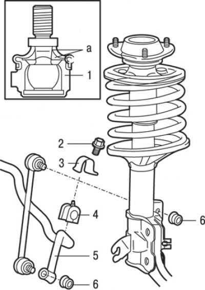
Fig. 15.33. Anti-roll bar on models produced since 1995: a - places of lubrication application; 1 – stabilizer bar for lateral stability; 2 – bolt (27 Nm); 3 – stabilizer bushing mounting bracket; 4 – bushing; 5 – anti-roll bar; 6 – nut (44 Nm)
2. Unscrew the bolt and disconnect the strut 1 (Fig. 15.33) from the anti-roll bar.
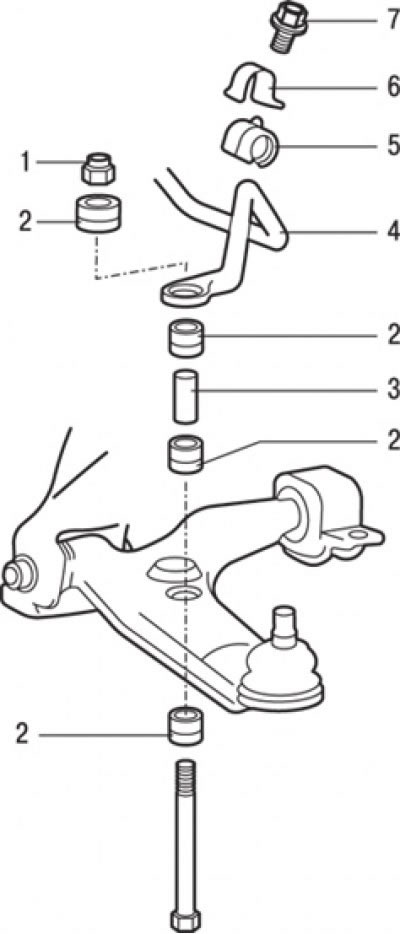
Fig. 15.34. Anti-roll bar on models produced since 1999: 1 – self-locking nut; 2 – rubber bushing of the anti-roll bar; 3 – sleeve; 4 – anti-roll bar; 5 – bushing; 6 – stabilizer bushing mounting bracket; 7 – bolt (27 Nm)
3. On vehicles manufactured since 1999, where the stabilizer is attached to the lower arm, unscrew the self-locking nut 1 (Fig. 15.34) and remove the rubber bushings 2 and sleeve 3.
4. Loosen the bolt and remove the bracket 3 (see Fig. 15.33) securing the stabilizer bushing.
5. Remove bushing 4 from the stabilizer.
6. Remove the anti-roll bar 5.
Installation
Installation is carried out in the reverse order of removal, taking into account the following.
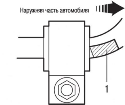
Fig. 15.35. When installing the stabilizer, the installation mark (1) should be on the right side
1. Position the stabilizer so that the alignment mark is on the right side. Then install the bushing so that the alignment mark is positioned as shown in Fig. 15.35.
2. Install the cross beam.