
English Русский
Български
Беларускі
Український
Српски
Hrvatski
Română
Polski
Slovenský
Magyar
Articles Bookmark Contacts Sitemap   
Company Audi Company Ford Company Hyundai Company Kia Company Mazda Company Mercedes-Benz Company Nissan
MitsubishiMan.ru


Home Colt Lancer Galant L200 Outlander Pajero Others
Lancer 9 (2000-2007, petrol) Lancer 3 and 5 (1984-1992)

Removal and installation the anti-roll bar (Mitsubishi Lancer 3)

  • Home
  • Lancer
  • 3 (1984-1992)
  • Chassis and running gear
  • Front suspension
  • Removal and installation the anti-roll bar
0
Contents: Removal ⤓ Installation ⤓

Removal


Raise the car, see item 29.
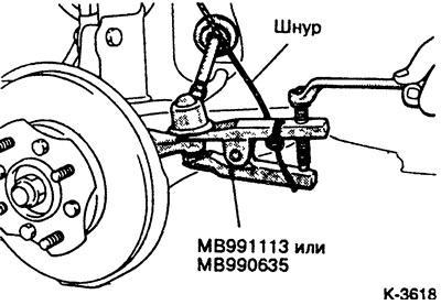


Press the steering tip joints out of the steering knuckle. Before doing this, pull out the safety pin and loosen the nut.
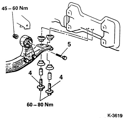


Loosen the rear mounting bolts "4" to the middle beam.

Loosen the bolt "5" of the silent block.
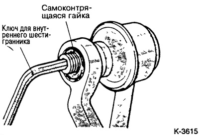


Unscrew the stabilizer from the connecting element (tie). At the same time, hold the hinge with an Allen key.


Note: On vehicles produced from January 19894 to August 1988, the stabilizer is connected by bushings with a through bolt, ball plates and rubber supports.


Loosen the stabilizer mounting clamps.

Pull the stabilizer together with the rubber supports through the hole for the steering rods of the body.

Installation


Before installation, check the condition of the rubber supports; replace cracked or damaged rubber supports.

Insert the stabilizer.
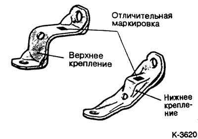


Note: Different clamps for fastening the rubber stabilizer mounts are installed on the left and right. To differentiate, take into account the distinctive markings. The right clamp is marked R, the left one is marked L.
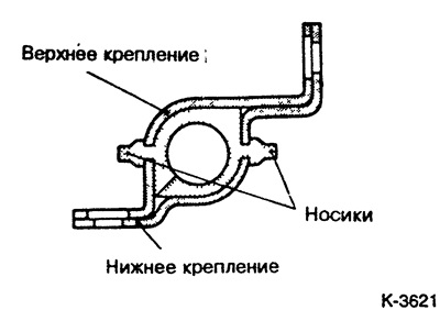


Attach the clamps of the rubber stabilizer supports to the bottom so that they securely clamp the noses of the stabilizer bushing.
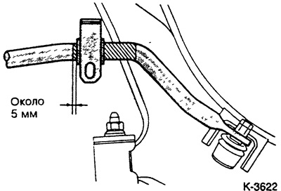


Position the stabilizer bushing on the left side so that it is approximately 5 mm from the end of the marked section of the stabilizer, see the figure. Tighten the clamps, then install the right bushing in the same way. Tighten the mounting bolts with a force of 25 Nm.
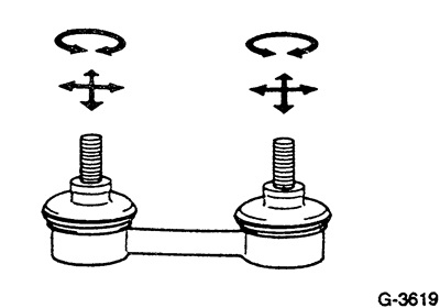


Check the ties. To do this, manually rotate the tie supports in all directions. They should turn easily, but without play.

Tighten the tie rods with new self-locking nuts to 70 Nm to the wishbone and stabilizer. Hold the joint with an Allen key when tightening the nuts.

Cars manufactured from 1.84 to 8.88: Attach the stabilizer with the bushing and rubber supports to the wishbone. Tighten the fastening nut so that the thread of the through bolt extends to 21-23 mm.


Tighten the rear silent block mounting bolt.

Tighten the bolts securing the middle beam.

Insert the steering tip head into the steering knuckle and tighten to 15 Nm. Insert and bend a new cotter pin. If the cotter pin does not fit, tighten the bolt (max. 35 Nm) until the hole for the cotter pin opens.

Lower the car.
This article is available at: russian, bulgarian, belarusian, ukrainian, serbian, croatian, romanian, polish, slovak, hungarian
This article was reviewed by: Dmitry Vasiliev
Share with friends:
◀ Previous
Lancer 3 and 5: Front suspension
Next ▶

Removal and installation the wishbone / Replacing the ball joint seal
Wishbone — device
Checking/disposal of shock absorber
Disassembling the front strut / removing and installing the shock absorber / coil spring
Front pillar — device
Drive shafts — device
Removal and installation the drive shaft
Checking/disassembling the drive shaft/replacing the seals
Wheel hub bearings — device
Similar materials for other Mitsubishi models

➤ Anti-roll bar — removal and installation Mitsubishi Colt 4 and 5 (1991-2003)
➤ Removal and installation the front anti-roll bar Mitsubishi Galant 6 and 7 (1987-1998)
➤ Front suspension anti-roll bar Mitsubishi L200 4 (2005-2014, diesel)
➤ Anti-lock braking system (ABS) diagram Mitsubishi Outlander 1 (2003-2008)
➤ Anti-roll bar Mitsubishi Pajero 1 and 2 (1982-1999)
➤ Anti-roll bar — removal and installation Mitsubishi Carisma (1995-2004)
Link in different formats to this article
Comments and feedback from visitors
No comments yet


Add up two numbers 23 + 47


Lancer 9 (2000-2007, petrol) 
  • General information
  • User manual
  • Maintenance
  • Power unit
  • Repair of MPI engines
  • Repair of GDI engines
  • Engine overhaul
  • Cooling and lubrication system
  • MPI fuel injection system
  • GDI fuel injection system
  • Intake and exhaust system
  • Starting and charging system
  • Transmission
  • Automatic gearbox
  • Variator (CVT)
  • Drive shafts and gearbox
  • Chassis and running gear
  • Front suspension
  • Rear suspension
  • Steering
  • Brake system
  • Body and interior
  • Doors, locks and windows
  • Exterior (external elements)
  • Interior (internal elements)
  • Electrical equipment
  • Heater and air conditioner
  • Security system SRS
  • Equipment and devices
  • Wiring diagrams (saloon)
  • Wiring diagrams (wagon)
Lancer 3 and 5 (1984-1992) 
  • General information
  • Maintenance
  • Power unit
  • Engine repair
  • Lubrication system
  • Cooling system
  • Ignition system
  • Fuel system
  • Carburetor
  • Fuel injection
  • Diesel power system
  • Exhaust system
  • Transmission
  • Clutch
  • Car gearbox
  • Chassis and running gear
  • Front suspension
  • Rear suspension
  • Steering
  • Brake system
  • Wheels and tires
  • Body and interior
  • Exterior (external elements)
  • Interior (internal elements)
  • Heating system
  • Electrical equipment
  • Equipment and devices
  • Power devices
  • Electrical circuits
MitsubishiMan.ru © 2018–2026 • Mobile version • Articles about Mitsubishi • Contacts • Sitemap: EN BG BY UA RS HR RO PL SK HU • Site search • Bookmark
Colt 2 and 3 (1983-1993) · Colt 4 and 5 (1991-2003) · Colt 5 (1995-2003) · Lancer 3 and 5 (1984-1992) · Lancer 9 (2000-2007) · Galant 5 (1983-1989) · Galant 6 and 7 (1987-1998) · L200 4 (2005-2014) · Outlander 1 (2003-2008) · Pajero 1 and 2 (1982-1999) · Pajero 4 (2006-2021) · Carisma (1995-2004) · Space Star (1998-2005) ·
This resource sets cookies 🍪 to avoid bothering you with repeated data entry.