



Contents: Removal ⤓ Installation ⤓
Caution: The vehicle must not be moved with the drive shafts removed, as the lack of axial tension may damage the rolling elements of the hub bearings. If it is necessary to move the vehicle, install the drive shafts.
Removing the joint from the gearbox side differs for shafts with and without a center bearing.
The designations in the text refer to Figure K-3623.
Removal
Squeeze out the decorative cap.
If present, carefully knock off the hub cap with a plastic hammer.
Straighten and pull out cotter pin "1" with pliers.
Loosen the fastening nut "2". At the same time, have the assistant press the foot brake pedal so that the hub does not turn.
Caution: The vehicle must be on the ground. High turning force. Risk of accident!
Loosen the wheel nuts on the vehicle while it is on the ground.
Mark the position of the wheel disc on the wheel hub with paint. This ensures that the balanced wheel can be reinstalled in its original position.
Raise the front of the car, see item 29.
Remove the wheel.
Drain the oil from the gearbox, see paragraph 32.2.
Loosen nut "2" of the hub and remove it with spacer washer "3".
Unscrew nut "4" and press ball joint "5" down, see item 14.6.
Press the joint "7" of the steering tip, see p. 16.4.
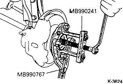
Press the drive shaft out of the wheel hub using a regular puller. The service station uses the MB-990241 puller for this purpose.
Drive shaft without middle bearing
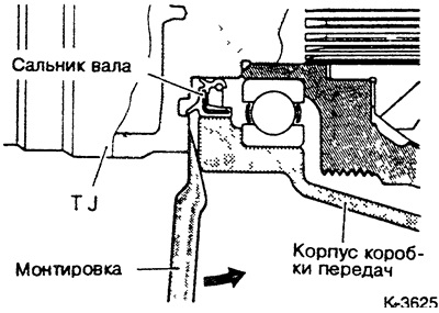
Insert the crowbar between the joint and the gearbox housing. Tilt the crowbar, thereby pressing the joint. If necessary, you can press the shaft out of the gearbox grip with a short jerk of the crowbar. Do not pull on the drive shaft, as this may damage the constant velocity joint! Do not insert the crowbar too far, so as not to damage the seal.
Drive shaft with center bearing (partially on cars produced from 1.84 to 8.88)
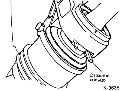
Remove the safety ring from the middle bearing.
Using a plastic hammer, lightly tap the ball joint plate to remove the drive shaft.
Caution: Pressing with a pry bar may damage the center bearing.
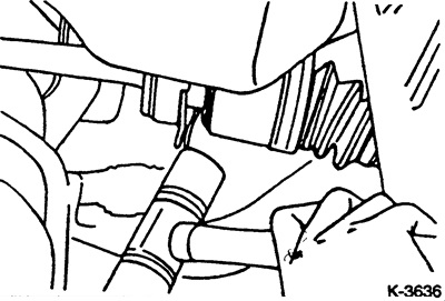
Check the ease of movement of the middle bearing.
Installation
If present, press the middle bearing until it is fully seated in the bearing housing. Then secure the bearing with a compression ring.
Before installation, check the seals for wear.
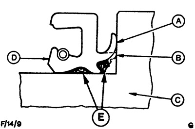
A - new sealing sponge;
B - worn sealing lip;
C - wheel hub or drive shaft;
D - oil seal;
E - grease.
Remove the worn seal. If necessary, drill a hole in the seal and, having screwed a screw of the appropriate diameter into the hole, pull out the seal, holding the screw with pliers.
Attention: If the seal is defective or worn, check the integrity of the rollers and bearing races and replace if necessary.
Coat the new seal with grease as shown in the figure and press the seal evenly using a tube of the appropriate diameter.
Clean and lightly lubricate the spline and threads of the drive shaft.
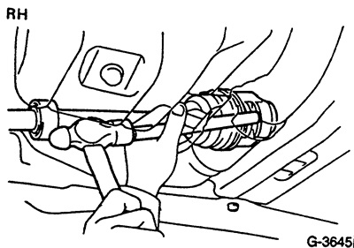 | 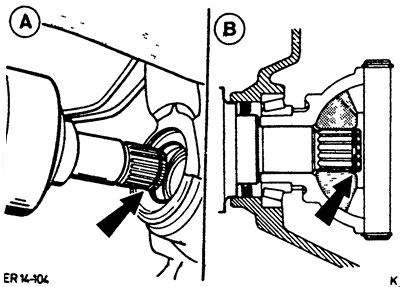 |
Insert the drive shaft with a new retaining ring "arrow A" into the splined connection of the bevel drive gear and press it in with a hammer and brass rod until it clicks "arrow B". Check the perfect fit of the shaft by lightly pulling and pressing. It should not be possible to pull it out by hand.
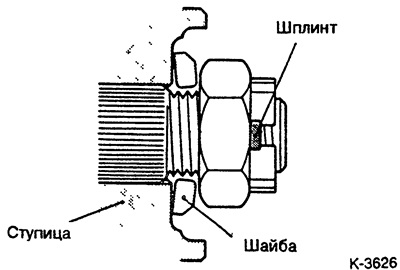
Place the spacer washer as shown in the figure and screw on the fastening nut without tightening it.
Secure the ball joint with a tightening torque of 70 Nm.
Tighten the steering tip joint to a tightening torque of 30 Nm and install a new cotter pin.
Install the wheel taking into account the marking of its position relative to the hub. Lower the car and cross-tighten the wheel nuts, tightening torques see item 19.4.
Tighten the hub nut with a force of at least 200 Nm. If the holes for the cotter pin in the nut and in the shaft do not match, tighten the nut again (up to 260 Nm) until the holes match. A new cotter pin must be installed.
Fill the gearbox with oil, see paragraph 32.2.
If removed, carefully install the hub cap.
If possible, urgently check the alignment angles of the front wheels of the vehicle.