



Contents: Removal ⤓ Installation ⤓
Removal
Loosen the wheel nuts on both front wheels while they are on the ground.
Mark the position of the wheel disk on the wheel hub with paint. This ensures that the balanced wheel can be reinstalled in its original position.
Raise the front of the car, see item 29.
Remove the wheel.
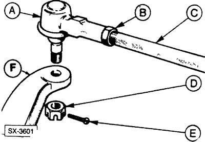
Disconnect the steering joint "A" from the steering arm "F" by pulling out the cotter pin "E" and loosening the castle nut "D". B is the lock nut, C is the steering rod.
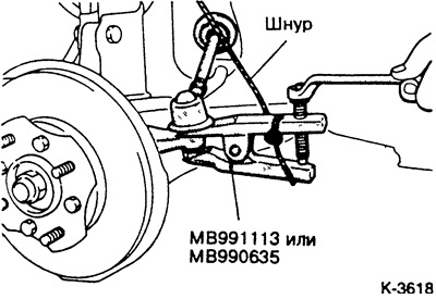
Press the steering joint with a regular puller.
Loosen the lock nut and remove the steering tip from the steering rod.
Note: Count the number of turns and screw the steering tip back into place when installing it again.
Installation
Screw the steering tip onto the steering rod by the counted number of turns. Do not tighten the lock nut yet.
Insert the joint into the steering arm.
Tighten the lock nut to 30 Nm and insert a new cotter pin. If it does not fit into the hole, do not loosen the nut, but tighten it before the cotter pin enters the hole.
Install the wheel, observing the markings made relative to the hub. Lower the car and tighten the wheel nuts crosswise. Tightening torque see item 19.4.
Rock the car to settle the suspension.
Check the alignment and tighten the lock nut on the steering tip to 50 Nm.
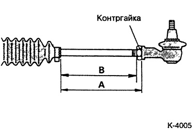
When replacing the tie rod or tie rod end, adjust the tie rod end joint to the following dimensions and then tighten the lock nut.
Mechanical steering
Cars produced from 1.84 to 8.88:
- size A: 172.5 - 174.5 mm
Cars produced from 9.88 to 4.89:
size A:
- type A: 192 - 194 mm;
- type B: 193 - 195 mm.
Cars produced from 4.89 to 3.92:
- size B, front wheel drive: 184 mm;
- rear wheel drive: 174 mm.
Power steering
Cars produced from 1.84 to 8.88:
- size A: 170.5 mm
Cars produced from 9.88 to 4.89:
- size A: type A: 190 - 192 mm
Cars produced from 4.89 to 3.92:
- size B, front wheel drive: 184 mm;
- rear wheel drive: 174 mm.
(The article was taken from the website: mitsubishiman.ru)