



Inner constant velocity joint and cover
Double offset joint (DOJ)
Disassembly
1. Remove the drive shaft from the vehicle (see section 10).
2. Secure the drive shaft in a vice. The jaws of the vice should be covered with wooden pads or rags to avoid damaging the shaft.
3. Using a small screwdriver, bend back the tab of the cover clamp and remove the clamp from the cover (see illustration).
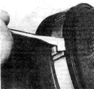
11.3. Bend back the petals of the cover clamps with a small screwdriver, remove the clamps from the cover
4. Slide the cover onto the shaft and remove the wire ball holder from the outer race (see illustration).
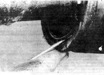
11.4. Remove the wire ball holder from the outer race...
5. Slide the outer race off the inside of the joint (see illustration).
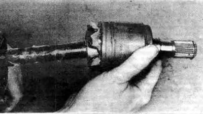
11.5a... then remove the outer race from the inner bearing assembly
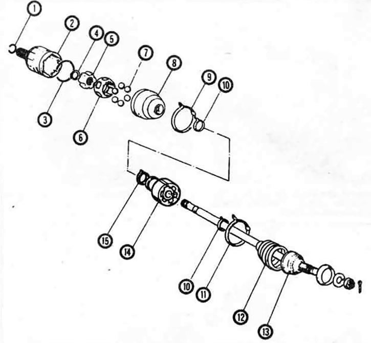
11.5b. Elements of the constant velocity joint drive shaft - exploded view. 1. Spring washer (always replace), 2. Inner CV joint outer race, 3. Wire ball retainer, 4. Circlip, 5. Inner race, 6. Cage, 7. Balls, 8. Inner boot, 9. Boot clamp, 10. Boot clamp, 11. Boot clamp, 12. Outer boot, 13. Outer CV joint and axle assembly, 14. Dynamic damper (left side only), 15. Dynamic damper clamp (left side only)
6. Remove the spring ring from the shaft groove using special pliers (see illustration).
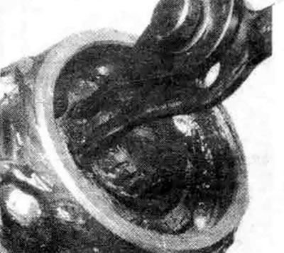
11.6. Using special pliers, remove the spring ring from the end of the axle
7. Mark the inner race and separator so that they can be installed in their original positions during assembly (see illustration).
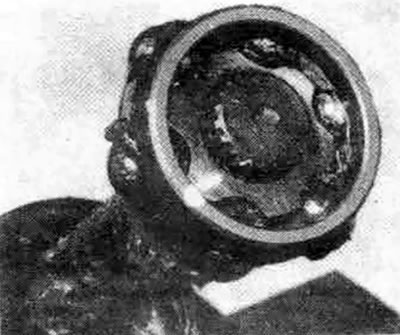
11.7 Place alignment marks on the inner race and separator to indicate which side should face the end of the shaft during assembly
8. Remove the inner part of the joint from the shaft.
9. Using a screwdriver or a wooden block, remove the balls from the cage (see illustration). Be careful not to scratch the inner race, the balls, or the cage.
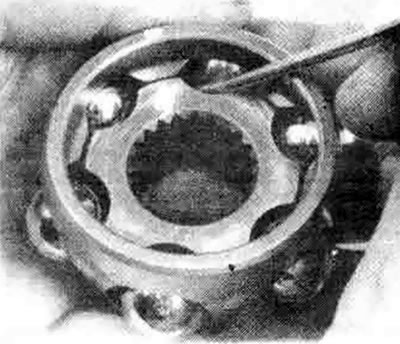
11.9. Using a screwdriver, remove the balls from the separator - do not scratch them
Note: If the inner part of the joint is difficult to disassemble, do not disassemble it. Clean it and remove grease in the assembled state.
10. Align the planes of the inner race with the separator windows and remove the race from the separator (see illustration).
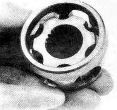
11.10a. Align the planes of the inner ring with the separator windows
Inspection
11. Clean the parts from grease with solvent. Inspect the separator and races for pitting, cracks and other signs of wear and damage. Shiny, polished spots are not a defect and will not reduce the characteristics of the constant velocity joint.
Assembly
12. Insert the inner race into the separator. Check the alignment of the marks, which should be on the same side. However, it is not necessary to set the marks opposite each other.
13. Insert the balls into the separator windows with your thumb (see illustration).
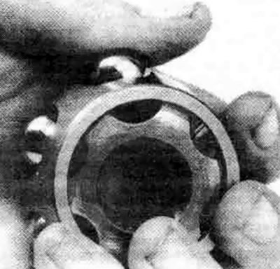
11.13 Insert the separator balls through the windows using only the force of the thumb
14. Wrap the shaft splines with electrical tape to prevent damage to the boot (see illustration). Place the small boot clamp and boot on the shaft, then remove the electrical tape
15. Install the inner race assembled with the separator on the shaft with the side with the larger diameter or the separator protrusion (and previously applied marks) towards the end of the axle.
16. Install the snap ring into the groove. Ensure that it is fully seated by pressing down on the inner race and separator assembly.
17. Using the CV joint grease supplied with the new boot, hand pack the race and separator until the assembly is completely filled with grease (see illustration). Place any remaining grease in the outer race and boot.
18. Place the outer race onto the inner race and install the wire retainer in place.
19. Remove excess grease from the boot groove on the outer race. Insert the small diameter of the boot into the groove of the axle. Place the other end of the boot on the outer race and adjust the length of the hinge by moving the race in or out (see illustration).
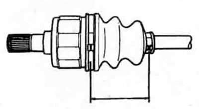
11.19. Adjust the length of the constant velocity joint (distance between the boot clamps) before tightening the clamps (see specification in this Chapter)
20. After adjusting the axle length, release the pressure from the boot by inserting a blunt screwdriver between the boot and the outer race (see illustration). Do not damage the boot with the tool.
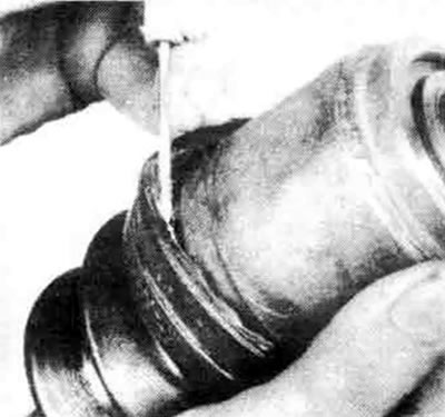
11.20. Release the pressure from the boot by inserting a small blunt screwdriver between the boot and the outer race
21. Replace the boot clamps (see illustration).
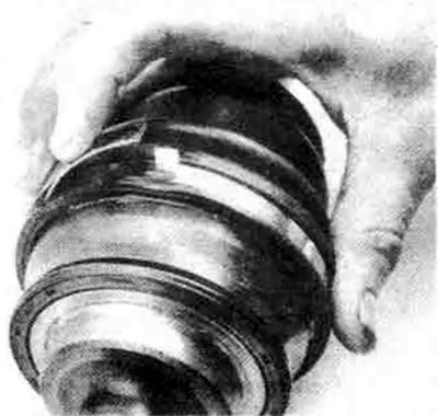
11.21a. To install new clamps, press the tongue and...
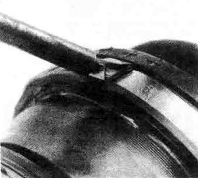
11.21b....fold the petals over it to secure it
22. Install a new spring washer onto the inner joint pin (see Illustration 10.7).
23. Install the drive shaft in place as described in section 10.
TJ joint
24. Cut the boot clamps and slide the boot toward the center of the drive shaft (see illustration). Mark the universal joint housing and drive shaft so that they can be installed in their original positions, then remove the housing from the axle.
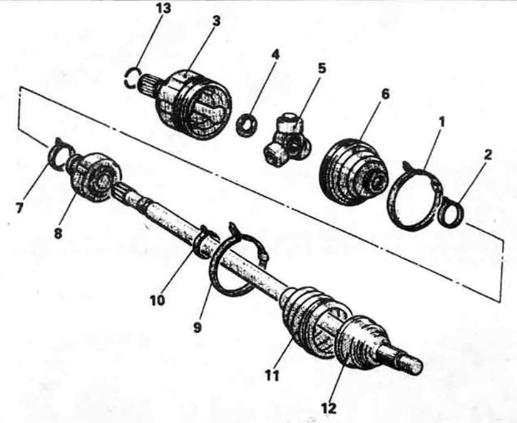
11.24. Exploded view of the joint with a crosspiece assembled with the axle. 1. Clamp, 2. Clamp, 3. Crosspiece housing, 4. Spring ring, 5. Crosspiece, 6. Boot, 7. Dynamic damper clamp (left side only), 8. Dynamic damper (left side only), 9. Boot clamp, 10. Boot clamp, 11. Boot, 12. Outer constant velocity joint (non-separable), 13. Spring washer
25. To secure during removal and installation, wrap the crosspiece bearings with electrical tape.
26. Remove the crosspiece assembly from the axle by removing the snap ring from the end of the axle and sliding the crosspiece off the drive shaft (see illustration).
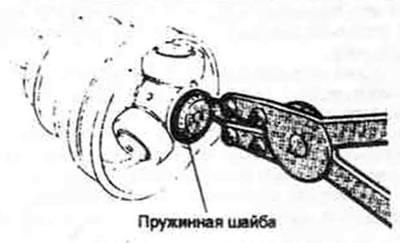
11.26. Remove the spring washer and slide the crosspiece off the axle
27. Remove the boot from the axle.
28. Remove all traces of old grease from the housing and the spider. Carefully disassemble each spider section one at a time and clean the needle bearings in solvent. Inspect the rollers, spider, bearings and housing for deep scratches, pitting and other signs of excessive wear. Apply constant velocity joint grease to the inside surfaces of the bearings to help lock the needle bearings in place while reassembling the spider.
29. Wrap the drive shaft splines with electrical tape to prevent damage to the boot, then place the small clamp and boot onto the shaft.
30. Place half of the grease from the new cover kit into the housing, and place the rest into the cover.
31. Install the crosspiece bearing.
32. Install the crosspiece housing.
33. Insert the boot into the sealing grooves of the housing and axle, then adjust the length of the joint (see Illustration 11.19). Reinstall the boot clamps, then reinstall the drive shaft as described in section 10.
Outer constant velocity joint and cover
Disassembly
34. Remove the inner constant velocity joint from the drive shaft and disassemble it.
35. If you are disassembling the left drive shaft outer joint, mark the relative positions of the dynamic damper and the axle. Open the dynamic damper clamp and remove the damper from the axle.
36. Remove the outer constant velocity joint boot clamps. Remove the boot from the shaft.
Inspection
37. Thoroughly rinse the inner and outer constant velocity joints in solvent and blow them out with compressed air if possible.
Note: Since the outer joint is not disassemblable, it is difficult to remove all the old grease and solvent from the bearings after cleaning. But it is important to do a good job, so take your time.
38. Rotate the constant velocity joint housing at an angle relative to the drive shaft so that the balls, inner race, and separator are visible. Check the wear of the ball and race surfaces. If the parts are damaged or worn, replace the drive shaft.
Assembly
39. Place the new outer boot on the drive shaft. Wrap the splines of the shaft with electrical tape to prevent damage to the boot. Using the constant velocity joint grease supplied with the new boot, pack the joint until it is completely filled with grease and put the remainder in the boot. Install the boot in the mounting seats and secure it with clamps.
40. If you are overhauling the left drive shaft, install the dynamic damper, taking into account the marks made during disassembly. Secure the damper with a clamp.
41. Clean and assemble the inner constant velocity joint following the instructions in this section, then reinstall the drive shaft as described in section 10.