Contents: Removal and installation ⤓ Examination ⤓ Checking the moment of the beginning…⤓ Replacing the rear lower arm bushing ⤓
Removal and installation
− The parts are removed in the order of numbers shown in the figure "Removing the lower arm of the front suspension".
- When removing parts, pay attention to the operation of disconnecting the lower arm from the subframe.
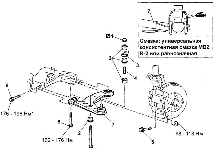
Removal the lower arm of the front suspension. 1 - lock nut, 2 - rubber bushing of the stabilizer, 3 - stabilizer bar, 5 - connection of the lower arm and steering knuckle, 6 - connection of the lower arm and cross beam assembly, 7 - lower arm assembly.
Note: It is only necessary to pre-tighten the bolt marked with the sign, and the final tightening should be done on an unloaded vehicle after lowering it onto its wheels.
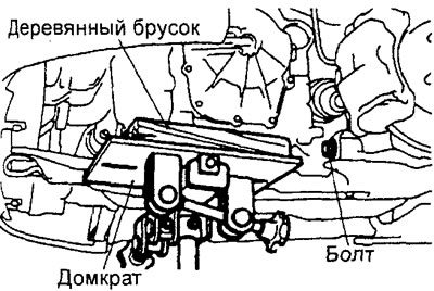
To make it easier to separate the lower arm from the subframe, jack up the transmission using a transmission jack.
− Installation of parts is carried out in the reverse order of removal.
- When installing the parts, pay attention to the operation of installing the lock nut.
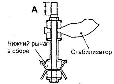
Tighten the lock nut so that the length "A" of the protruding part of the stabilizer mounting bolt corresponds to the nominal value.
Nominal value - 20.5 - 23.5 mm
- After installing the parts, perform the following operations.
a) Check the protective cover for cracks or damage.
b) Check and adjust the front wheel alignment angles.
Examination
1. Check the bushing for wear and damage.
2. Check the lower arm for bending or damage.
3. Check the condition of all bolts.
4. Check the condition of the protective boot of the lower arm ball joint (see the corresponding subsection in the "Additional checks" section).
Attention:
- - Cracks and damage to the protective cover can cause damage to the ball joint.
- - If the protective cover is damaged during maintenance work, replace the protective cover with a new one and repeat the check.
Checking the moment of the beginning of rotation of the ball joint pin of the lower arm
1. Rock the ball joint pin several times, screw the nut onto it, and, using a special torque wrench, measure the moment the ball joint pin begins to rotate.
Nominal value - 0 - 3.9 Nm
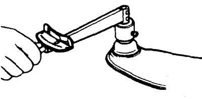
2. If the measured value exceeds the nominal value or the rotation of the ball joint is difficult or uneven (sticking), replace the lower arm assembly.
Replacing the protective cover of the lower arm ball joint
Please note: the protective cover should only be replaced if it is damaged during maintenance work.
1. Remove the protective cover.
2. Apply general purpose grease to the working edge of the boot and place the grease inside the new protective boot.
Lubricant - universal consistent grease MB2, R-2 or equivalent
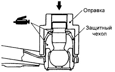
3. Using a special tool, install the protective cover onto the ball joint until it is fully seated.
4. Make sure the protective cover is positioned as shown in the figure. Check that there are no unusual protrusions or stretching of the protective cover.
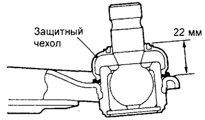
5. Check the protective cover for cracks or damage.
The article is based on data from the website mitsubishiman
Replacing the rear lower arm bushing
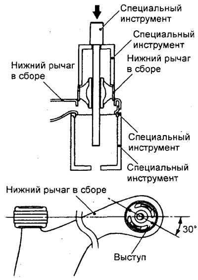
1. Using a special tool, remove the bushing from the lower arm.
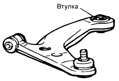
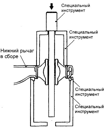
2. When pressing in, install the bushing so that its protrusion is located as shown in the figure.
3. Using the special tool, press the lower arm bushing so that the edge of its outer part is flush with the surface of the lower arm assembly.