



Caution: On models with the Supplemental Restraint System (SRS), set the front wheels to the straight-ahead position and remove the key from the ignition before removing the steering gear. Failure to do so may damage the SRS coil wire and cause the airbag to deploy unexpectedly, resulting in serious injury.
Removal
− Before removing parts, perform the following operations.
a) Remove the lower protective covers of the power unit.
b) Remove the steering wheel and the driver's airbag module (see chapter "Steering"),
c) Remove the SRS coil wire (see chapter "SRS passive safety system").
d) Remove the central longitudinal beam (see chapter "Powertrain mounts").
d) Remove the exhaust pipe (see chapter "Intake and exhaust systems").
− The parts are removed in the order of numbers shown in the figure "Removing the anti-roll bar".
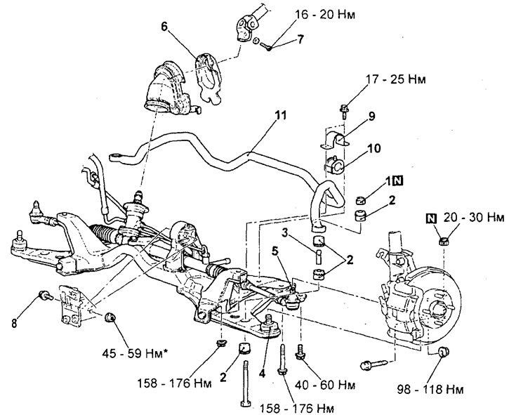
Removal the anti-roll bar. 1 - lock nut, 2 - rubber bushing of the stabilizer strut, 3 - bushing, 4 - ball joint of the lower arm, 5 - ball joint of the tie rod end, 6 - steering column casing, 7 - steering shaft bolt, 8 - connecting bolt of the rear support of the power unit, 9 - stabilizer mounting bracket, 10 - bushing, 11 - anti-roll bar.
- When removing parts, pay attention to the following operations.
1. Disconnecting the lower arm of the front suspension from the steering knuckle.
Using a special tool, disconnect the lower arm from the steering knuckle.
Attention:
- To prevent the puller from bouncing off, it must first be tied with a cord.
- Just loosen the nut on the ball joint pin, do not remove the nut completely.
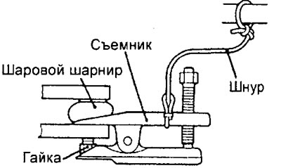
Note: it is only necessary to pre-tighten the nut marked with the sign, and the final tightening should be done on an unloaded vehicle after lowering it onto its wheels.
2. Removing the stabilizer mounting bracket, bushing, stabilizer strut and anti-roll bar.
Note: Perform the following operations before removing the stabilizer mounting bracket, bushing, stabilizer link and stabilizer bar.
a) Place the transmission telescopic stand under the cross beam, remove the bolts and nuts securing the cross beam.
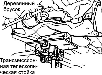
b) Lower the cross member until the retainers, bushings, stabilizer struts and stabilizer bar can be removed.
Caution: Do not lower the cross member too low to avoid deforming the power steering return hose mounting bracket.
Examination
1. Check the bushings for wear, damage or deterioration.
Original version of the article on the website (MITSUBISHIMAN.ru)
2. Check the anti-roll bar for damage or wear.
3. Check the condition of all bolts.
4. Check the condition of the ball joint protective cover.
Attention:
- - Cracks and damage to the protective cover may cause damage to the ball joint.
- - If the protective cover is damaged during maintenance work, replace the protective cover with a new one and repeat the check.
Installation
− Install the parts in the reverse order of removal. When installing the parts, pay attention to the following operations.
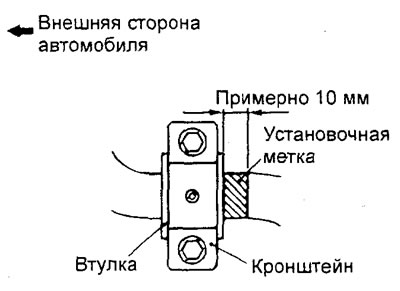
1. Installing the anti-roll bar, bushing and anti-roll bar mounting bracket.
Position the bracket so that the distance between the edge of the bushing and the edge of the stabilizer installation mark on the longitudinal axis of the vehicle is approximately 10 mm.
2. Installing the lock nut.
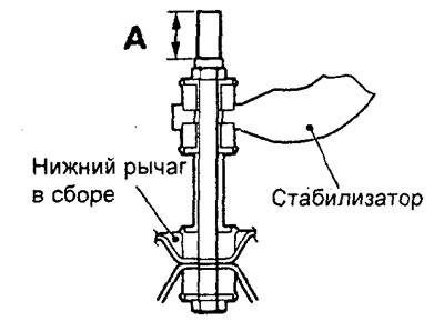
Tighten the self-locking nut until the length "A" of the stabilizer bar protruding part reaches the nominal value.
Nominal value - 20.5 - 23.5 mm
− After completing the installation of the parts, perform the following operations.
a) Install the exhaust pipe (see chapter "Intake and exhaust systems").
b) Install the central longitudinal beam (see chapter "Powertrain mounts").
c) Install the SRS coil wire (see chapter "SRS passive safety system").
d) Install the steering wheel and driver's airbag module (see chapter "Steering"),
d) Check the protective covers for mechanical damage,
e) Check the central position of the steering wheel when the front wheels are parallel to the longitudinal axis of the vehicle.
g) Checking and adjusting the front wheel alignment angles.
c) Install the lower protective covers of the power unit.