



Attention:
- - Never attempt to disassemble or repair the airbag module or coil wire. Replace them if faulty.
- - Do not drop the air bag module or coil wire, or allow water, oil, or fuel to come into contact with them. If dents, cracks, deformation, or corrosion are found, replace the air bag module and coil wire with new ones.
- The airbag module should be stored in a clean, dry place on a flat, horizontal surface with the protective cover facing up.
- - Do not place foreign objects on the airbag module.
- − Do not allow the air bag module to reach temperatures above 93°C.
- - After the front airbags have been deployed, their modules must be replaced with new ones. Check the spiral wire and replace it with a new one if it is faulty.
Removal
− Before you start removing parts, pay attention to the following operations:
- a) Disconnect the wire from the negative terminal of the battery and insulate the wire connector.
Caution: After disconnecting the battery cable, wait at least 60 seconds before proceeding with further work.
- b) If necessary, remove the lower steering column cover.
- c) (Passenger air bag module) If necessary, remove the instrument panel assembly.
- d) (Passenger air bag module) Remove the air distribution duct if necessary.
− The parts are removed in the order of the numbers indicated in the figure "Removing the front airbag modules and spiral wire".
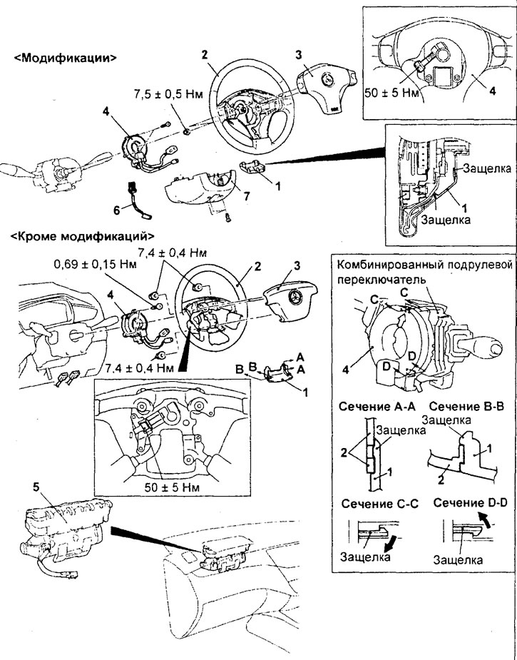
Removal the front airbag modules and coil wire.1 - Steering wheel side cover, 2 - Steering wheel, 3 - Driver's front airbag module, 4 - Spiral wire, 5 - Passenger's front airbag module, 6 - Additional connector (models with automatic transmission), 7 - Lower steering column cover.
- When removing parts, pay attention to the following operations:
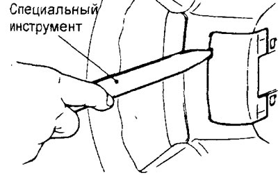
1. Removing the steering wheel side cover.
Using a special tool, remove the steering wheel side cover as shown in the figure.
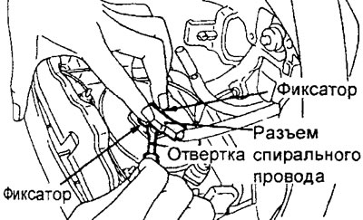
2. Removing the steering wheel and driver's front airbag module assembly.
a) (Modifications) To disconnect the coil wire connector from the air bag module, use a screwdriver to release the clips as shown in the figure.
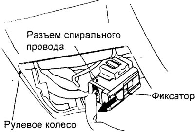
b) (Except for modifications) To disconnect the coil wire connector from the air bag module, pull the lock as shown in the figure.
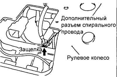
c) (Modifications) To disconnect the additional coil wire connector, detach the latch as shown by the arrow in the figure.
d) Insert the tool head with the socket wrench (insert) into the place indicated by the arrow in the figure, then unscrew the steering wheel mounting bolt and remove it together with the driver's front airbag module.
Note: Use a tool head with an 8mm Allen key (insert) at least 75mm long.
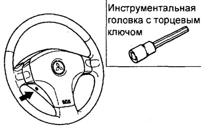
Modifications
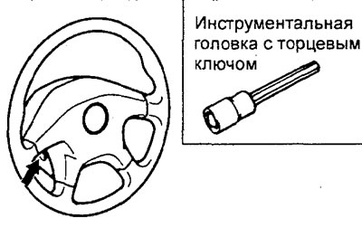
Besides modifications.
3. Removing the passenger front airbag module.
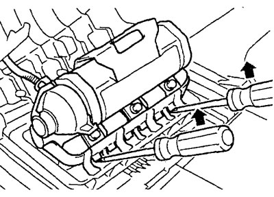
Using a flat-head screwdriver, release the two latches of the passenger front air bag module simultaneously as shown in the illustration.
Caution: Do not damage the passenger front airbag module mounting components.
Examination
Caution: Never attempt to measure the resistance of the air bag module (igniter) circuit, even with the recommended tester. Measuring the resistance of the circuit with a tester may cause unintended deployment of the air bag.
1. Visually inspect the condition of the airbag modules and the coil wire (see the corresponding subsection in the "SRS System Maintenance" section).
2. Checking the spiral wire circuit.
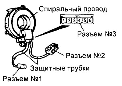
a) (Modifications) Check for a closed circuit between connector #1 and terminal "1" of connector #3.
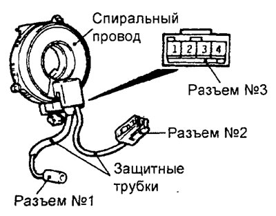
b) (Except for modifications) Check for a closed circuit between connector No.1 and terminal "4" of connector No.3.
c) Install special probes into connector No.2.
Caution: To avoid damaging the connector, insert special probes only from the back side of the connector (from the wire side).
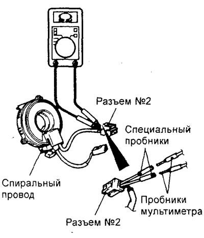
d) Connect the multimeter to the special probes and check for voltage.
Installation
- Before installing parts:
- a) Temporarily connect the cable to the negative terminal of the battery.
- b) Connect the tester to the diagnostic connector.
Caution: When connecting or disconnecting the tester, the ignition key must be in the "OFF" position.
- c) Turn the ignition on and check that the SRS system is functioning normally (except for the fault code for the removed air bag module).
- d) Turn the ignition switch to the "LOCK" position, disconnect the wire from the negative terminal of the battery and insulate the wire connector.
Caution: After disconnecting the battery cable, wait at least 60 seconds before proceeding with further work.
− Installation of parts is carried out in the reverse order of removal.
- When installing parts, please pay attention to the following:
1. Installation of spiral wire.
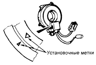
a) Turn the coil wire fully clockwise, then turn it counterclockwise approximately 3.75 turns (modifications) and 3 turns (except modifications) to align the alignment marks of the coil wire position indicator
Caution: If the alignment marks of the coil wire are not completely aligned, the steering wheel may be restricted when turning the vehicle, or the flat cable may separate from the coil wire, causing the SRS system to malfunction and serious injury to the driver.
b) Set the front wheels of the vehicle parallel to the longitudinal axis of the vehicle and install the spiral wire into the steering column combination switch.
2. Installing the steering wheel and airbag module assembly.
a) Before installing the steering wheel, make sure that the alignment marks on the coil wire position indicator are completely aligned.
Caution: Before installing the steering wheel, check that the wires of the spiral wire are not pinched or tangled.
b) After securing the steering wheel, turn it fully in both directions to check that the steering operates correctly.
- After installing the parts, perform the following operations:
- a) (Passenger air bag module) Install the air distribution duct.
- b) (Passenger air bag module) Install the instrument cluster assembly.
- c) Install the lower steering column cover.
- d) Connect the wire to the negative terminal of the battery.
- d) Check the operation of the SRS indicator.