



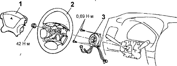
Fig. 19.111. Driver's airbag and spiral wire: 1 - driver's airbag; 2 - steering wheel; 3 - spiral wire
Removal
- Set the front wheels to straight ahead and remove the key from the ignition switch.
- On the back of the steering wheel, remove the two airbag mounting screws (Fig. 19.112). Do not remove the screws from the holders.
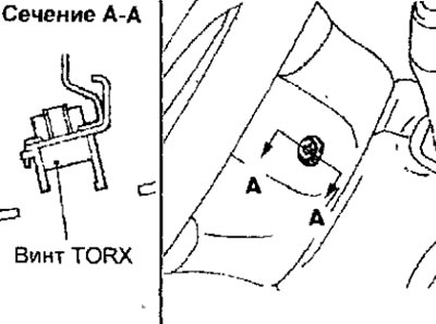
Fig. 19.112. Location of the driver's airbag mounting screw
- Disconnect the connector that connects the coil wire to the airbag. When disconnecting the coil wire connector, move the locking latch outward, which will release the connector (Fig. 19.113). Use a flat-blade screwdriver to gently pry the connector apart.
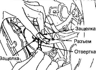
Fig. 19.113. Disconnecting the connector connecting the spiral wire to the airbag
- Loosen the steering wheel mounting nut. Apply alignment marks to the end of the steering shaft and the steering wheel and remove the steering wheel using a puller.
- Remove the screws and remove the upper and lower steering column covers.
- Disconnect the electrical connectors from the multifunction switch. Remove the three bolts and remove the multifunction switch.
- In the reverse order to that shown in Figure 19.114, unscrew the screws securing the spiral wire.
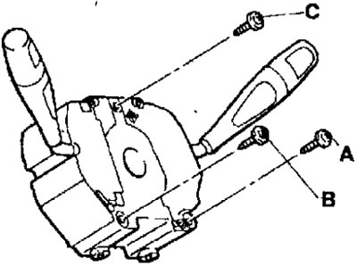
Fig. 19.114. Sequence of tightening the screws for fastening the spiral wire
[Article reprinted from the website mitsubishiman.ru]
Examination
- Check the airbag cover for dents, cracks or deformation.
- Check the connectors for damage and the connector contacts for deformation.
Checking the spiral wire
- If any defect is found, replace the spiral wire
- Check the electrical connectors and protective tube for damage and oxidation of the connector contacts.
- Check the conductivity between contact 3 of connector 1 of the spiral wire and connector 2 (Fig. 19.115).
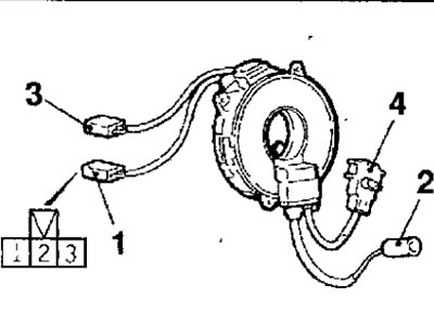
Fig. 19.115. Numbering of spiral wire connectors and location of connector contacts
- Align the color marks of the special tool MB991613 connector 4 with the recess of connector 2 of the spiral wire (arrow in Figure 19.116) and connect connectors 2 and 4.
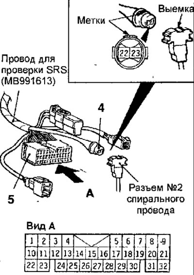
Fig. 19.116. Connecting connector 4 of the special tool MB991613 to connector 2 of the spiral wire
- Check the conductivity between contacts 22 and 23 of the special tool MB991613 and connector No.5.
Installation
- Installation is carried out in the reverse order of removal, taking into account the following.
- Align the installation marks of the spiral wire in the middle position, for which, after turning the inner sleeve of the spiral wire clockwise until it stops, turn it in the opposite direction by 3 and 4/5 turns until the installation marks are aligned (Fig. 19.117).
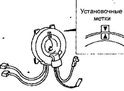
Fig. 19.117. Alignment of the installation marks of the spiral wire
- After setting the front wheels to the straight-ahead position, reinstall the spiral wire and secure it with the screws, tightening them in the sequence shown in Figure 19.114.
Warning: When installing the steering wheel, make sure the coil wire harness is not pinched or tangled.
- Before installing the steering wheel, set the front wheels to the straight-ahead position and align the alignment marks on the coil wire.
- Install the steering wheel and driver's airbag. When installing the airbag, connect the spiral wire connector to the module. Make sure the connector is securely connected by checking that the connector clips snap into place. Install the airbag mounting screws and tighten them to 9 N·m (Fig. 19.118).
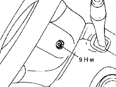
Fig. 19.118. Location of the driver's airbag mounting screw
- When turning the steering wheel, make sure that it rotates smoothly and without any extraneous noise.
Warning: The SRS will not operate properly if any component of the system is not installed correctly.
Post-installation check
- Connect the cable to the negative terminal of the battery.
Warning: To avoid damage to electrical equipment, turn the ignition switch to the LOCK position before connecting or disconnecting the MUT-II.
- Connect the MB991502 device to the diagnostic connector.
- Turn on the ignition.
- Diagnose the SRS system and make sure it is working properly.
Warning: Disconnect the negative battery cable and isolate it, then wait 60 seconds for the capacitor to discharge. Otherwise, the airbag may deploy unexpectedly, which may cause personal injury.
- Turn off the ignition. Disconnect the wire from the negative terminal of the battery and insulate it.