



Checking the SRS indicator
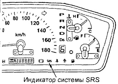
1. Turn the ignition switch to the "ON" position and check that the SRS indicator comes on.
2. Check that the SRS indicator comes on for approximately 7 seconds and then goes out and remains off for at least 5 seconds.
3. If the SRS indicator operates differently than specified, check the fault codes.
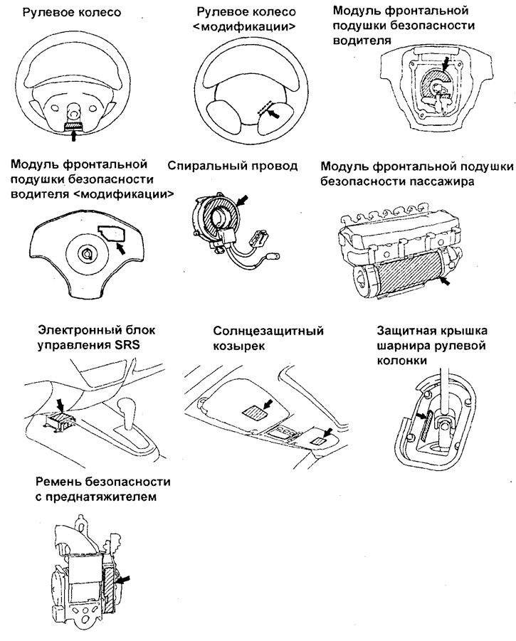
Visual inspection of system components on the vehicle
Attention:
- - If any of the above system components are found to be defective during visual inspection, replace the defective part.
- If any SRS parts or components are installed incorrectly, the SRS system may not operate properly, which could result in serious injury or death to the driver and front seat passenger.
1. Preparation for testing.
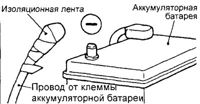
Turn the ignition switch to the "LOCK" position. Disconnect the wire from the negative terminal of the battery and insulate the connector of the disconnected wire.
Caution: After disconnecting the negative battery cable, wait at least 60 seconds before proceeding with further work.
Warning labels
All components of the vehicle's SRS system and related components have appropriate labels describing the maintenance requirements. When servicing the SRS system, follow the requirements on the labels. If the labels are damaged or dirty, replace them with new ones.
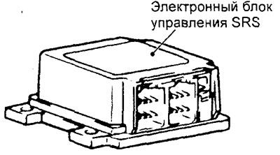
2. Checking the SRS electronic control unit.
a) Check the SRS control unit housing and brackets for dents, cracks, deformation or corrosion.
b) Check the connectors and retainer for damage, deformation, and traces of rust on the connector terminals. Replace the SRS electronic control unit if a defect is detected as a result of a visual inspection.
3. Check the driver's front airbag module and the front passenger's front airbag module, steering wheel and spiral wire.
a) Remove the airbag modules, steering wheel and coil wire.
Caution: Removed airbag modules should be stored in a clean, dry place with the protective cover (front side) facing up.
b) Check the surfaces of the airbag protective pads for dents, cracks or deformations.
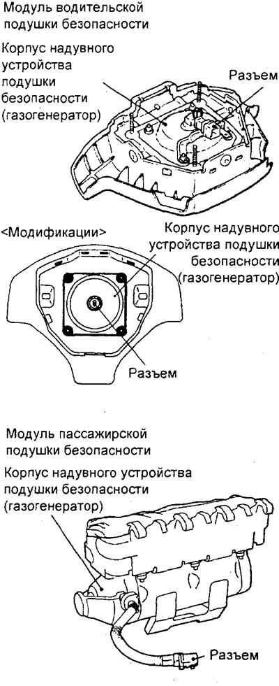
c) Check the condition (absence of kinks and pinching) of the wire harnesses, absence of damage or deformation of the connectors and their terminals.
d) Check the inflatable device housings (gas generators) for dents, cracks or deformations.
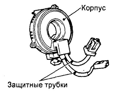
d) Check the connectors and protective tubes of the spiral wire for damage and the connector terminals for deformation.
e) Visually inspect the coil cable housing for damage.
g) Install the spiral wire in place (see the relevant section).
h) Install the upper and lower steering column covers, steering wheel and driver front air bag module.
i) Check the ease of rotation and the absence of extraneous sounds when turning the steering wheel.
k) Check the steering wheel play.