
English Русский
Български
Беларускі
Український
Српски
Hrvatski
Română
Polski
Slovenský
Magyar
Articles Bookmark Contacts Sitemap   
Company Audi Company Ford Company Hyundai Company Kia Company Mazda Company Mercedes-Benz Company Nissan
MitsubishiMan.ru


Home Colt Lancer Galant L200 Outlander Pajero Others
Lancer 9 (2000-2007, petrol) Lancer 3 and 5 (1984-1992)

SRS Electronic Control Unit (Mitsubishi Lancer 9)

  • Home
  • Lancer
  • 9 (2000-2007, petrol)
  • Electrical equipment
  • Security system SRS
  • SRS Electronic Control Unit
0
Contents: Removal and installation ⤓ Examination ⤓
Attention:
  • Never attempt to disassemble or repair the SRS electronic control unit. Replace it if faulty.
  • - Do not drop, hit or vibrate the SRS electronic control unit. If dents, cracks, deformation or corrosion are found on the housing of the SRS electronic control unit, replace the unit with a new one.
  • - After the airbags have deployed, replace the SRS control unit with a new one.
  • - Never use an ohmmeter in the area where the SRS electronic control unit is located, use only special measuring devices.


Removal and installation


− Before you begin removing parts, perform the following operations:
  • a) Set the ignition switch to the "LOCK" position.
  • b) Disconnect the wire from the negative terminal of the battery and insulate the connector of the disconnected wire.

Caution: After disconnecting the battery cable, wait at least 60 seconds before proceeding with further work.

  • c) Remove the center console assembly.
  • d) Remove the electronic control unit of the engine and automatic transmission.

− The parts are removed in the order of the numbers indicated in the figure "Removing the SRS electronic control unit".
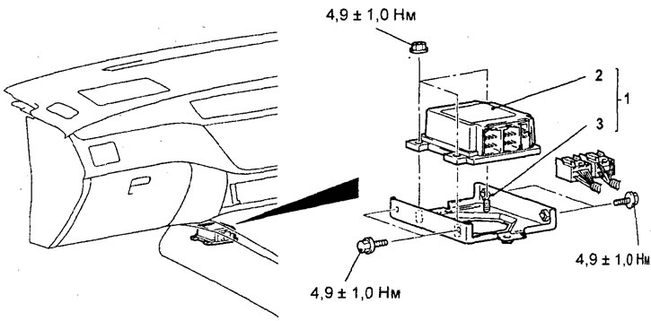


Removal the SRS electronic control unit. 1 - SRS electronic control unit assembly, 2 - SRS electronic control unit, 3 - SRS electronic control unit mounting bracket.


- Perform a visual inspection of the parts before installation.

Caution: If deformation, corrosion or damage is found on the body and bracket of the SRS electronic control unit or connectors and fasteners, replace them with new ones.


− Installation of parts is carried out in the reverse order of removal.

- After installing the parts, I performed the following operations:
  • a) Install the electronic control unit for the engine and automatic transmission.
  • b) Install the floor console assembly.
  • c) Connect the wire to the negative terminal of the battery.
  • d) Check the operation of the indicator: SRS.

Examination


1. Check the housing and bracket: SRS electronic control unit for dents, cracks, deformation or corrosion.

2. Check the connectors and retainer for damage, deformation and traces of rust on the connector terminals.

Caution: Replace the SRS control unit if a defect is found during visual inspection.
This article is available at: russian, bulgarian, belarusian, ukrainian, serbian, croatian, romanian, polish, slovak, hungarian
This article was reviewed by: Arseny Pavlov
Share with friends:
◀ Previous
Lancer 9: Security system SRS
Next ▶

SRS System Maintenance
Troubleshooting
Safety precautions during maintenance
General information about the passive restraint system (SRS)
Airbag modules and coil wire
Seat belt with pretensioner
Similar materials for other Mitsubishi models

➤ Electronic control unit ABS Mitsubishi Colt 5 (1995-2003, petrol)
➤ Removal and installation the ABS control unit Mitsubishi Galant 6 and 7 (1987-1998)
➤ Electronic Engine Control Unit (ECU) Mitsubishi L200 4 (2005-2014, diesel)
➤ Checking the electronic unit of the electric fan Mitsubishi Outlander 1 (2003-2008)
➤ Removal the ETACS electronic control unit Mitsubishi Pajero 4 (2006-2021)
➤ Panel and electronic control unit of air conditioning with… Mitsubishi Carisma (1995-2004)
Link in different formats to this article
Comments and feedback from visitors
No comments yet


Add up two numbers 29 + 27


Lancer 9 (2000-2007, petrol) 
  • General information
  • User manual
  • Maintenance
  • Power unit
  • Repair of MPI engines
  • Repair of GDI engines
  • Engine overhaul
  • Cooling and lubrication system
  • MPI fuel injection system
  • GDI fuel injection system
  • Intake and exhaust system
  • Starting and charging system
  • Transmission
  • Automatic gearbox
  • Variator (CVT)
  • Drive shafts and gearbox
  • Chassis and running gear
  • Front suspension
  • Rear suspension
  • Steering
  • Brake system
  • Body and interior
  • Doors, locks and windows
  • Exterior (external elements)
  • Interior (internal elements)
  • Electrical equipment
  • Heater and air conditioner
  • Security system SRS
  • Equipment and devices
  • Wiring diagrams (saloon)
  • Wiring diagrams (wagon)
Lancer 3 and 5 (1984-1992) 
  • General information
  • Maintenance
  • Power unit
  • Engine repair
  • Lubrication system
  • Cooling system
  • Ignition system
  • Fuel system
  • Carburetor
  • Fuel injection
  • Diesel power system
  • Exhaust system
  • Transmission
  • Clutch
  • Car gearbox
  • Chassis and running gear
  • Front suspension
  • Rear suspension
  • Steering
  • Brake system
  • Wheels and tires
  • Body and interior
  • Exterior (external elements)
  • Interior (internal elements)
  • Heating system
  • Electrical equipment
  • Equipment and devices
  • Power devices
  • Electrical circuits
MitsubishiMan.ru © 2018–2026 • Mobile version • Articles about Mitsubishi • Contacts • Sitemap: EN BG BY UA RS HR RO PL SK HU • Site search • Bookmark
Colt 2 and 3 (1983-1993) · Colt 4 and 5 (1991-2003) · Colt 5 (1995-2003) · Lancer 3 and 5 (1984-1992) · Lancer 9 (2000-2007) · Galant 5 (1983-1989) · Galant 6 and 7 (1987-1998) · L200 4 (2005-2014) · Outlander 1 (2003-2008) · Pajero 1 and 2 (1982-1999) · Pajero 4 (2006-2021) · Carisma (1995-2004) · Space Star (1998-2005) ·
This resource sets cookies 🍪 to avoid bothering you with repeated data entry.