
English Русский
Български
Беларускі
Український
Српски
Hrvatski
Română
Polski
Slovenský
Magyar
Articles Bookmark Contacts Sitemap   
Company Audi Company Ford Company Hyundai Company Kia Company Mazda Company Mercedes-Benz Company Nissan
MitsubishiMan.ru


Home Colt Lancer Galant L200 Outlander Pajero Others
Lancer 9 (2000-2007, petrol) Lancer 3 and 5 (1984-1992)

Toe-in control arm, upper and lower arms (Mitsubishi Lancer 9)

  • Home
  • Lancer
  • 9 (2000-2007, petrol)
  • Chassis and running gear
  • Front suspension
  • Toe-in control arm, upper and lower arms
0
Contents: Removal ⤓ Examination ⤓ Installation ⤓ Replacing the lower arm bushing ⤓

Removal


− The parts are removed in the order of numbers shown in the figure "Removing the toe-in adjustment lever, upper and lower arms".
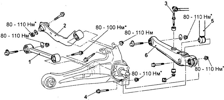


Removal the toe adjustment lever, upper and lower arms. 1 - toe-in adjustment lever, 2 - upper lever, 3 - stabilizer strut connection, 4 - lower lever and trailing arm connection bolt, 5 - lower shock absorber mount, 6 - lower lever.


Note: To prevent damage to the bushings, it is only necessary to pre-tighten the nuts and bolts marked with the sign, and to perform the final tightening on an unloaded vehicle after lowering it onto its wheels.


- When removing parts, pay attention to the following operations.

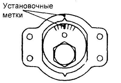
1. Removing the toe adjustment lever.

Apply alignment marks as shown in the illustration, then remove the toe adjustment lever.


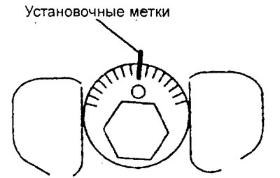
2. Removing the lower arm.


Apply alignment marks as shown in the figure, then remove the lower arm.


2. Removing the bolt securing the lower arm to the rear wheel knuckle:

a) Place a wooden block under the lower arm as shown in the figure. Using a jack, compress the rear suspension spring and remove the lower arm-to-rear wheel knuckle bolt.
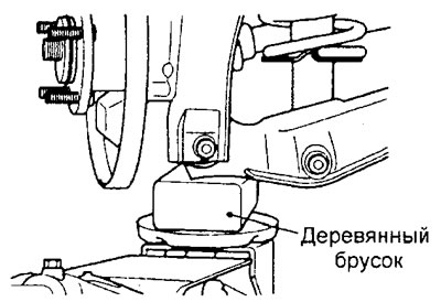


b) Slowly lower the jack and remove the spring.

Examination


1. Check the bushings for wear, damage or deterioration.

2. Check the toe adjustment arm, upper arm and lower arm for bending or damage.

3. Check the condition of all bolts.

Installation


− Installation of parts is carried out in the reverse order of removal.

- When installing parts, pay attention to the following operations:

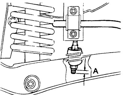
1. Installing the stabilizer bar.


Install the stabilizer bar so that the length of its protruding threaded part "A" is within the nominal value.

Nominal value "A" - 6-8 mm


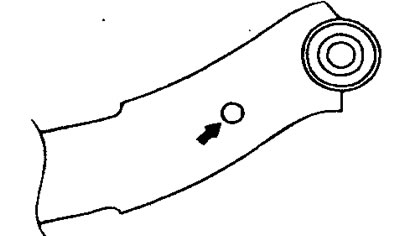
2. Installing the upper arm.

When installing the upper arm, make sure that the hole marked with an arrow in the figure is located on the body side.


Replacing the lower arm bushing


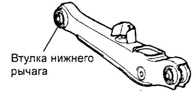
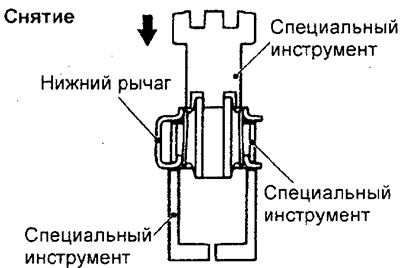
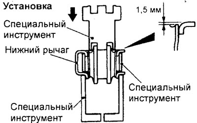
Using a special tool, press the bushing out of the lower arm. After pressing, the distance between the edge of the outer part of the bushing and the lower arm should be 1.5 mm.

Caution: When replacing the lower arm bushing, take into account the differences on the opposite sides of the bushing.


This article is available at: russian, bulgarian, belarusian, ukrainian, serbian, croatian, romanian, polish, slovak, hungarian
This article was reviewed by: Arseny Pavlov
Share with friends:
◀ Previous
Lancer 9: Front suspension
Next ▶

Transverse stability stabilizer
Lower control arm of the front suspension
Front suspension strut
Checking and adjusting the front wheel alignment angles
Trailing arm
Similar materials for other Mitsubishi models

➤ Lower Control Arm Rear Bushing (Bracket Models) —… Mitsubishi Colt 4 and 5 (1991-2003)
➤ Removal and installation the upper control arms of the rear… Mitsubishi Galant 6 and 7 (1987-1998)
➤ Upper control arm front suspension Mitsubishi L200 4 (2005-2014, diesel)
➤ Installing the Upper Control Arm/Steering Rod Assembly Mitsubishi Outlander 1 (2003-2008)
➤ Upper control arm — removal and installation Mitsubishi Pajero 1 and 2 (1982-1999)
➤ Adjusting, upper and lower rear suspension arms Mitsubishi Carisma (1995-2004)
Link in different formats to this article
Comments and feedback from visitors
No comments yet


Add up two numbers 20 + 31


Lancer 9 (2000-2007, petrol) 
  • General information
  • User manual
  • Maintenance
  • Power unit
  • Repair of MPI engines
  • Repair of GDI engines
  • Engine overhaul
  • Cooling and lubrication system
  • MPI fuel injection system
  • GDI fuel injection system
  • Intake and exhaust system
  • Starting and charging system
  • Transmission
  • Automatic gearbox
  • Variator (CVT)
  • Drive shafts and gearbox
  • Chassis and running gear
  • Front suspension
  • Rear suspension
  • Steering
  • Brake system
  • Body and interior
  • Doors, locks and windows
  • Exterior (external elements)
  • Interior (internal elements)
  • Electrical equipment
  • Heater and air conditioner
  • Security system SRS
  • Equipment and devices
  • Wiring diagrams (saloon)
  • Wiring diagrams (wagon)
Lancer 3 and 5 (1984-1992) 
  • General information
  • Maintenance
  • Power unit
  • Engine repair
  • Lubrication system
  • Cooling system
  • Ignition system
  • Fuel system
  • Carburetor
  • Fuel injection
  • Diesel power system
  • Exhaust system
  • Transmission
  • Clutch
  • Car gearbox
  • Chassis and running gear
  • Front suspension
  • Rear suspension
  • Steering
  • Brake system
  • Wheels and tires
  • Body and interior
  • Exterior (external elements)
  • Interior (internal elements)
  • Heating system
  • Electrical equipment
  • Equipment and devices
  • Power devices
  • Electrical circuits
MitsubishiMan.ru © 2018–2026 • Mobile version • Articles about Mitsubishi • Contacts • Sitemap: EN BG BY UA RS HR RO PL SK HU • Site search • Bookmark
Colt 2 and 3 (1983-1993) · Colt 4 and 5 (1991-2003) · Colt 5 (1995-2003) · Lancer 3 and 5 (1984-1992) · Lancer 9 (2000-2007) · Galant 5 (1983-1989) · Galant 6 and 7 (1987-1998) · L200 4 (2005-2014) · Outlander 1 (2003-2008) · Pajero 1 and 2 (1982-1999) · Pajero 4 (2006-2021) · Carisma (1995-2004) · Space Star (1998-2005) ·
This resource sets cookies 🍪 to avoid bothering you with repeated data entry.