Removal and installation
- Parts are removed in the order of the numbers shown in the figure "Removing the front suspension strut assembly".
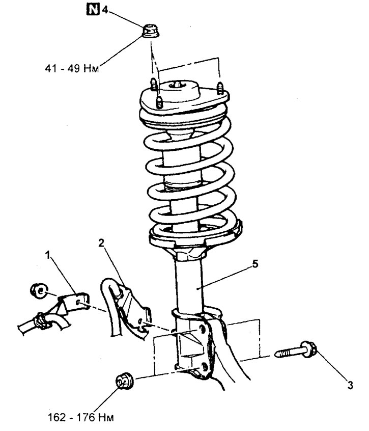
Removing the front suspension strut assembly. 1 - bracket for fastening the wiring harness of the front wheel speed sensor (models with ABS). 2 - bracket for fastening the brake hose, 3 - bolt for fastening the front suspension strut and steering knuckle, 4 - nut for fastening the front suspension strut, 5 - front suspension strut assembly.
− Installation of parts is carried out in the reverse order of removal.
− After completing the installation of the parts, perform the following operations:
- A) Check up a condition of protective covers of spherical hinges and a protective cover of a rack.
- b) Check and adjust the front wheel alignment.
Disassembly
− Dismantling is carried out in the order of the numbers indicated in the figure "Dismantling the front suspension strut".
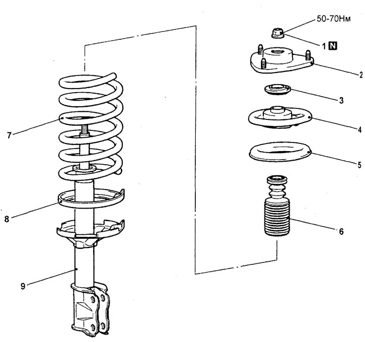
Dismantling the front suspension strut. 1 - locknut, 2 - strut damping support, 3 - bearing, 4 - upper spring seat, 5 - upper spring pad, 6 - compression stroke buffer, 7 - front suspension strut spring, 8 - lower spring seat, 9 - front suspension strut.
− When removing parts, pay attention to the operation to remove the locknut.
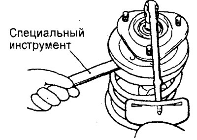
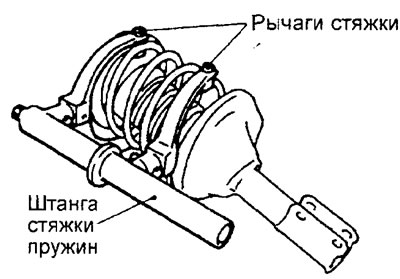
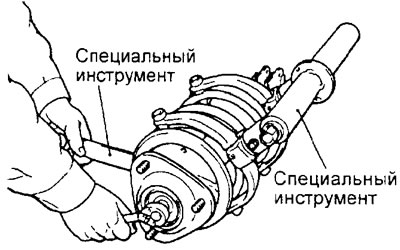
A) Using the special tool, compress the strut spring.
Attention:
- - Install the special tool arms symmetrically so that their maximum length does not exceed the setting limits (spring length).
- - Do not use pneumatic tools (impact wrench) when tightening the special tool bolt.
b) While holding the upper spring cup with the special tool, loosen the lock nut.
Caution: do not use pneumatic tools (impact wrench).
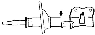
Gas removal
1. Fully extend the strut stem.
2. Using a drill, drill a gas vent hole in the cylinder in the area shown in the figure.
Attention: it is safe to release gas, but when drilling, metal chips may fly out.
Assembly
- Assembly is carried out in the reverse order of disassembly.
− When assembling, pay attention to the installation procedure of the self-locking nut.
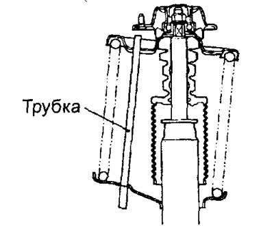
A) Compress the spring with the special tool and temporarily tighten the self-locking nut.
b) Align the hole in the top spring cup and the hole in the bottom spring cup on the same line.
Note: Use a suitable tube.
V) Correctly position the edges of both coils of the spring in the grooves of the seats, then loosen the special tool.
G) Using the special tool, tighten the locknut to the specified torque.
Note: do not use pneumatic tools (impact wrench) when tightening the locknut.
Tightening torque - 50 - 70 Nm