



Contents: Preparatory operations ⤓ Beating ⤓ Convergence ⤓ Steering wheel angles ⤓ Camber, longitudinal and transverse…⤓ Side slip ⤓ Checking the ball joint protective…⤓
Preparatory operations
1. When checking the front wheel alignment angles using a special device, always place the vehicle on a flat horizontal surface so that the front wheels are in a straight-ahead position.
2. Before checking, make sure that the front suspension, steering and wheels are in good technical condition. Also, check that the car is on a flat horizontal surface, the wheels are in a straight-ahead position and the tire pressure is normal.
Caution: Worn or damaged front and rear suspension components must be replaced before checking and adjusting wheel alignment.
Beating
1. Raise the wheels of one of the vehicle axles and install safety stands under the vehicle.
2. Measure the wheel disc runout using a dial indicator as shown in the figure.
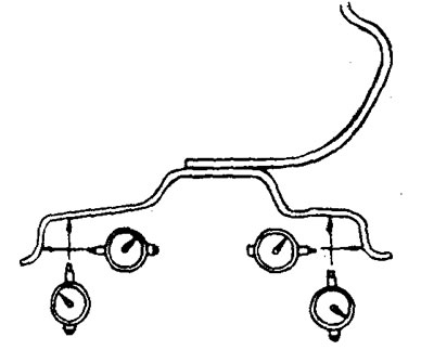
3. Replace the wheel if its runout exceeds the maximum permissible value.
Maximum permissible runout:
- radial - 1.0 mm
- axial - 1.2 mm
- Tightening torque - 90-110 Nm
Original source of information MitsubishiMan.ru
Convergence
1. Wheel alignment (the difference in dimensions B - A or the sum of angles α + β) is adjusted by rotating the steering rod ends.
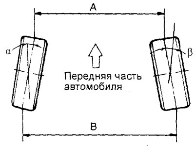
2. Measure the toe-in of the front wheels. The nominal toe-in is 1 ±2 mm
3. If the front wheel alignment does not correspond to the nominal value, then perform adjustment.
a) Loosen the tie rod end locknuts.
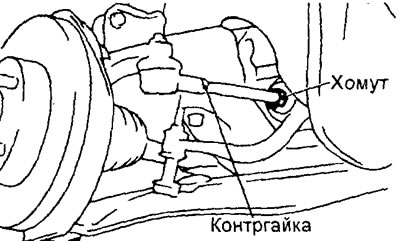
b) To change the wheel alignment, rotate the right and left steering rod ends by equal angles in opposite directions.
c) Tighten the tie rod end locknuts.
Steering wheel angles
1. Place the front wheels on a turning radius measuring stand and measure the turning angles of the steered wheels.
Nominal value:
- Inner wheel - 40°40' ±1°30'
Outer wheel (for reference):
- sedan models - 33°
- station wagon models - 33°20'
2. If the steering angles do not correspond to the nominal values, then the front wheel toe-in is probably not adjusted. Adjust the toe-in and check the steering angles again.
Camber, longitudinal and transverse tilt of the steering axis
1. Measure the camber, caster and lateral tilt of the front wheel pivot axis using a special tool.
Nominal value:
Sedan models:
Models from 05.2000:
- Camber — 0°00' ±30'
- Longitudinal tilt of the pivot axis - 2°50' ±30'
Models from 07.2000:
- Camber — 0°05' ±30'
- Longitudinal tilt of the rotation axis - 2°45' ±30'
Station wagon models:
2WD models except low-slung models:
- Camber — 0°00' ±30'
- Longitudinal tilt of the pivot axis - 2°35' ±30'
Low-slung models:
- Camber — -0°05' ±30'
- Longitudinal tilt of the rotation axis - 2°45' ±30'
4WD models:
- Camber — 0°05' ±30'
- Longitudinal tilt of the rotation axis - 2°35' ±30'
Note: The difference between the measured values for the left and right wheels should be no more than 0°30'.
Attention:
- For vehicles with cast aluminum wheels, install the wheel alignment sensor on the drive shaft using a special adapter. Tighten the special adapter to the same tightening torque as the drive shaft mounting nut.
Tightening torque - 226 +49 Nm
- It is prohibited to load the front wheel hub bearings with the weight of the vehicle when the wheel drive shaft mounting nuts are loose.
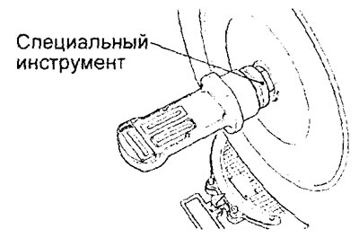
2. If the front wheel camber does not correspond to the nominal value, then check the front suspension units and replace deformed or damaged parts.
Side slip
Measure lateral slip on a special slip tester.
Nominal value - 0 ±3 mm
Checking the ball joint protective covers
1. Press your finger on the protective cover and check the cover for wear, damage, cracks, abrasions and deterioration in technical condition.
2. If mechanical damage to the protective cover is detected, replace the lower arm of the front suspension assembly or the front suspension stabilizer bar.
Caution: Cracks or damage to the protective boot may result in damage to the ball joint.
Note: If the protective cover has been damaged during maintenance work, replace the protective cover with a new one and repeat the check.