
English Русский
Български
Беларускі
Український
Српски
Hrvatski
Română
Polski
Slovenský
Magyar
Articles Bookmark Contacts Sitemap   
Company Audi Company Ford Company Hyundai Company Kia Company Mazda Company Mercedes-Benz Company Nissan
MitsubishiMan.ru


Home Colt Lancer Galant L200 Outlander Pajero Others
Carisma (1995-2004) Space Star (1998-2005)

Lower control arm of the front suspension (Mitsubishi Space Star)

  • Home
  • Mitsubishi
  • Space Star (1998-2005)
  • Chassis and running gear
  • Suspension and drive shafts
  • Lower control arm of the front suspension
0
Contents: Removal ⤓ Examination ⤓ Installation ⤓

Removal


Warning: Parts marked with * in Figure 14.32 must be pre-tightened and final tightened after the vehicle has been lowered onto its wheels in an unladen condition.
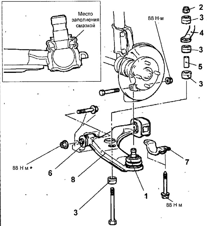


Fig. 14.32. Lower arm of the front suspension: 1 - lower arm ball joint; 2 - self-locking nut; 3 - rubber bushings for mounting the anti-roll bar; 4 - anti-roll bar; 5 - sleeve; 6 - front lower arm bushing; 7 - support bracket; 8 - lower arm assembly

  • Loosen the nut, remove the bolt and the ball joint pin of the lower arm from the steering knuckle (Fig. 14.32).
  • Loosen the self-locking nut and remove the rubber bushings and the sleeve securing the anti-roll bar to the lower arm of the front suspension.
  • Loosen the nut and remove the bolt securing the front lower arm bushing.
  • Remove 2 bolts and the lower arm rear bushing support bracket.
  • Remove the lower control arm assembly.

Examination


  • Check the rubber bushings for wear or damage.
  • Check the lower control arm for bending or cracks.
  • Check the support bracket for wear or damage.
  • Check the ball joint protective boot for cracks.
  • Check all bolts for bending or damage.

Checking the initial torque required to turn the lower arm ball joint pin


  • Rock the lower arm ball joint pin from side to side several times.
  • Install the special tool on the ball joint pin and use a torque wrench to measure the initial torque required to turn the lower arm ball joint pin (Fig. 14.33).
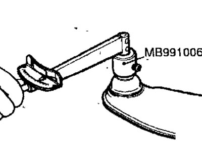


Fig. 14.33. Measuring the initial torque required to rotate the lower arm ball joint pin


Initial torque: 1.0-6.4 Nm

Torque: 1.0-2.5 Nm

  • If the torque exceeds the permissible values, replace the ball joint.
  • If the torque is significantly below the permissible value, the ball joint can be used repeatedly as long as it does not jam or have excessive play.

Checking the dust cover of the lower arm ball joint


  • Use your fingers to squeeze the dust cover and check for cracks or damage.
  • If the dust boot is cracked or damaged, replace the lower control arm ball joint.

Note: If the dust cover is cracked or damaged, the ball joint may also be damaged.


Replacing the rear lower arm bushing


  • Wet the connection between the lower arm shaft and the old bushing with soapy water and, using a screwdriver as a lever, remove the bushing.
  • Lubricate the hole in the new bushing with soapy water and install the new bushing in the position shown in Figure 14.34.
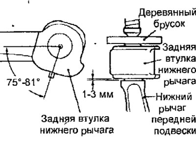


Fig. 14.34. Installation position of the rear bushing of the lower arm of the front suspension

  • Using a hammer and a wooden block, press the bushing onto the lower arm shaft.

Replacing the lower arm ball joint dust cover


  • Only if the dust cover is damaged accidentally during vehicle maintenance, replace it as follows.
  • Using a screwdriver blade, remove the spring ring and dust cover from the lower arm ball joint (Fig. 14.35).
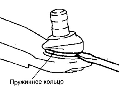


Fig. 14.35. Using a screwdriver to remove the ball joint protective boot retaining spring ring


  • Apply general purpose grease to the inside surfaces of the new dust cover.
  • Wrap the ball joint pin with plastic tape and place a dust cover on the joint.
  • Stop the spring ring securing the dust cover.
  • Use your fingers to squeeze the dust cover and check for cracks or damage.

Installation


  • Installation is carried out in the reverse order of removal, taking into account the following.
  • Install the anti-roll bar and tighten the self-locking nut so that the anti-roll bar mounting bolt protrudes above the nut as shown in Figure 14.36.
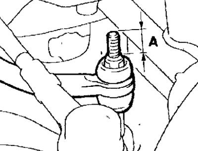


Fig. 14.36. Distance (A) of the stabilizer mounting bolt protrusion: A = 22 mm

  • Use your fingers to squeeze the dust cover and check for cracks or damage.
  • Adjust the front wheel alignment angles.
This article is available at: russian, bulgarian, belarusian, ukrainian, serbian, croatian, romanian, polish, slovak, hungarian
This article was reviewed by: Miroslav Rakov
Share with friends:
◀ Previous
Space Star: Suspension and drive shafts
Next ▶

Repair of the front suspension shock absorber
Front suspension shock absorber strut
Front wheel hub
Replacing the wheel mounting bolt
Checking the front wheel hub play
Anti-roll bar
Drive shafts
Repair of drive shafts
Rear suspension
Checking and adjusting the rear wheel alignment angles
Similar materials for other Mitsubishi models

➤ Lower control arm of the front suspension — description of… Mitsubishi Colt 5 (1995-2003, petrol)
➤ Lower control arm of the front suspension Mitsubishi Lancer 9 (2000-2007, petrol)
➤ Checking the condition of the lower ball joints of the… Mitsubishi Galant 6 and 7 (1987-1998)
➤ Lower control arm of the front suspension Mitsubishi L200 4 (2005-2014, diesel)
➤ Front Suspension Specifications and Testing Mitsubishi Outlander 1 (2003-2008)
➤ Lower control arm and bushing replacement Mitsubishi Pajero 1 and 2 (1982-1999)
Link in different formats to this article
Comments and feedback from visitors
No comments yet


Add up two numbers 30 + 11


Carisma (1995-2004) 
  • General information
  • User manual
  • Maintenance
  • Power unit
  • Petrol engines 4G9
  • Diesel engines FBQT
  • Diesel engines F9Q
  • Cooling system
  • Injection system (MPI)
  • Injection system (GDI)
  • Engine electrical equipment
  • Transmission
  • Clutch
  • Mechanical gearbox
  • Automatic gearbox
  • Chassis and running gear
  • Steering
  • Brake system
  • Front suspension and shafts
  • Rear suspension
  • Body and interior
  • Exterior (external elements)
  • Interior (internal elements)
  • Doors, locks and windows
  • Air conditioner
  • Electrical equipment
  • Equipment and devices
  • Headlights and lighting
  • Electrical circuits
Space Star (1998-2005) 
  • General information
  • User manual
  • Maintenance
  • Power unit
  • Petrol engines 4G9
  • Petrol engines 4G1
  • Diesel engines F9Q1
  • Cooling system
  • Fuel injection system GDI
  • Fuel injection system MPI
  • Diesel supply system F9Q1
  • Ignition system
  • Diesel preheating
  • Transmission
  • Clutch
  • Mechanical gearbox
  • Automatic gearbox
  • Chassis and running gear
  • Suspension and drive shafts
  • Brake system
  • Steering
  • Body and interior
  • Exterior (external elements)
  • Interior (internal elements)
  • Doors, locks and windows
  • Heating and air conditioning
  • Electrical equipment
  • Power devices
  • Equipment and devices
MitsubishiMan.ru © 2018–2026 • Mobile version • Articles about Mitsubishi • Contacts • Sitemap: EN BG BY UA RS HR RO PL SK HU • Site search • Bookmark
Colt 2 and 3 (1983-1993) · Colt 4 and 5 (1991-2003) · Colt 5 (1995-2003) · Lancer 3 and 5 (1984-1992) · Lancer 9 (2000-2007) · Galant 5 (1983-1989) · Galant 6 and 7 (1987-1998) · L200 4 (2005-2014) · Outlander 1 (2003-2008) · Pajero 1 and 2 (1982-1999) · Pajero 4 (2006-2021) · Carisma (1995-2004) · Space Star (1998-2005) ·
This resource sets cookies 🍪 to avoid bothering you with repeated data entry.