
Warnings
- On vehicles with ABS, when removing and installing the wheel speed sensor, be careful not to strike the sensor, otherwise it will be damaged.
- On vehicles with ABS, when removing and installing the drive shaft, be careful not to hit the ABS sensor rotor located on the BJ constant velocity joint housing, otherwise it will be damaged.
- Loosen the front wheel nut. Apply the parking brake, then raise the front of the vehicle and support it on stands. Remove the corresponding front wheel.
- On a vehicle with ABS Disconnect the connector, remove the bolt and remove the wheel speed sensor nepeflHefo (pic. 14.8).
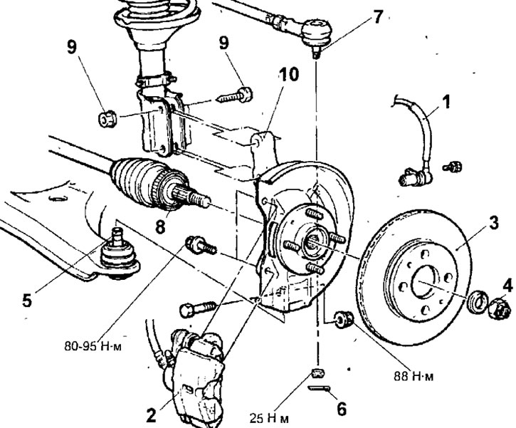
Pic. 14.8. Front wheel hub: 1 - front wheel speed sensor (vehicles with ABS); 2 - support; 3 - brake disc; 4 - nut for fastening the drive shaft, 216-255 Nm; 5 - ball joint of the lower arm; 6 - cotter pin; 7 - ball joint of the tie rod end; 8 - drive shaft; 9 - bolt and nut for fastening the steering knuckle to the front suspension strut, 88 Nm; 10 - steering knuckle and hub
- Remove the two bolts securing the caliper to the steering knuckle, lift the caliper up and secure it to the front suspension strut with soft wire.
- Remove the two screws and remove the brake disc from the front wheel hub.
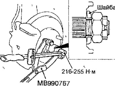
- Holding the hub from turning with a special tool, unscrew the drive shaft fastening nut (pic. 14.9).
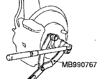
Pic. 14.9. Unscrewing the nut securing the drive shaft to the front wheel hub
Warning. After loosening the nut securing the drive shaft to the front wheel hub, do not install the car on the wheels, otherwise the hub bearing will be damaged.
- Remove the cotter pin and loosen the nut securing the ball joint pin of the tie rod end to the steering knuckle.
Warnings
- Do not loosen the nut securing the ball joint pin of the tie rod end to the steering knuckle. To prevent damage to the threads on the ball joint pin, use the special tool MB991113 or MB990635.
- To prevent the fall of the special tool MB991113 or MB990635, fix it with a cord on the front suspension stand.
- Install the special tool MB99111Z or MB990635 as shown in Figure 14.10, making sure that the jaws of the tool are parallel. Turn the special tool bolt to push the ball joint pin out of the steering knuckle, then loosen the nut and remove the ball joint pin from the steering knuckle.
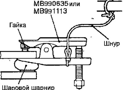
Pic. 14.10. Using a special tool to extrude the ball joint trunnion from the steering knuckle
- Loosen the nut, remove the bolt and lower arm ball joint pin from the steering knuckle.
- Using a special tool attached to the hub, press the drive shaft out of the front wheel hub (pic. 14.11). In the absence of a special tool with a kapron hammer, knock out the drive shaft from the front wheel hub. If the drive shaft is firmly seated in the front wheel hub, spray impregnating spray thinner into the spline area and then re-thread the nut until it is flush with the end of the shaft. Hit the nut with a brass hammer to knock the drive shaft out of the hub.
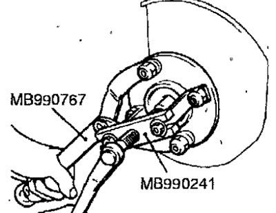
Pic. 14.11. Using a special tool to extrude the drive shaft from the front wheel hub
- Turn away nuts and get bolts of fastening of a shock-absorber rack to a rotary fist and remove a rotary fist with a nave from the car.
Examination
- Check the hub for cracks and signs of excessive wear on the splines.
- Check the seal for damage.
- Check the steering knuckle for cracks.
- Check the hub bearing for damage. If there is play between the steering knuckles and the outer race of the bearing or the hub and the inner races of the bearing, replace the bearing or damaged parts.
Installation
- Installation is carried out in the reverse order of removal, taking into account the following.
- Install the washer under the nut securing the drive shaft to the hub as shown in Figure 14.12.
Pic. 14.12. The installation position of the washer under the nut of the drive shaft to the hub
- Using a torque wrench, tighten the nut securing the drive shaft to the hub, while holding the hub from turning with a special tool. Before tightening the driveshaft-to-hub nut, make sure that the front wheel hub bearing is not loaded by the weight of the vehicle.
Disassembly
- Remove the inner seal (pic. 14 13).
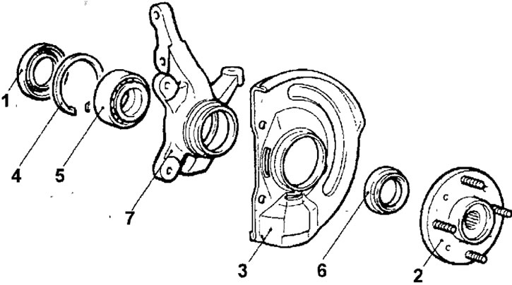
Pic. 14.13. Front wheel hub: 1 - inner gland; 2 - hub; 3 - protective casing of the brake; 4 - retaining ring; 5 - hub bearing; 6 - outer gland; 7 - steering knuckle
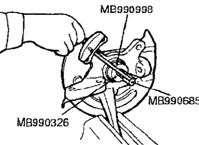
- Attach the special tools MB 991056 or MB 991355 to the steering knuckle (pic. 14.14). Insert the special tool MB990998 through the hole into the hub and, screwing the nut onto it, remove the hub from the steering knuckle.
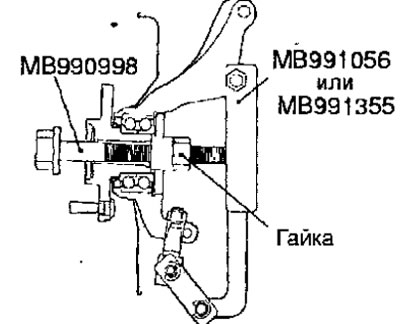
Pic. 14.14. Using special tools MB990998 and MB991056 or MB991355 to remove the hub from the steering knuckle
Warning. When removing the hub, replace the hub bearing.
- Remove the circlip securing the bearing outer ring from the steering knuckle.
- Remove the bearing outer seal.
- To capture the outer part of the inner ring of the bearing using the jaws of a special puller, break the outer seal in two places, as shown in Figure 14.15.
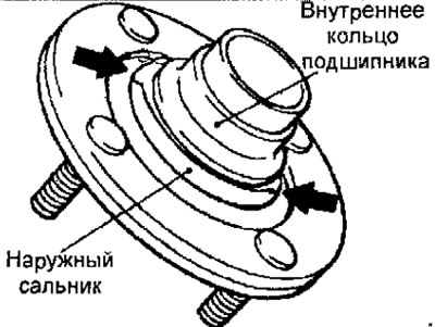
Pic. 14.15. Break points of the outer seal
- Using a special puller MB990810, remove the inner ring of the bearing from the hub (outer part) (pic. 14.16). When removing the bearing inner race, hold the hub to prevent it from falling to the floor
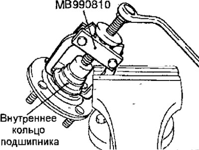
Pic. 14.16. Using a special puller MB990810 to remove the bearing inner race from the hub.
- Install the outer part of the inner ring removed from the hub into the bearing and then remove the bearing with a special puller (pic. 14.17).
Pic. 14.17. Using a bearing puller
- Remove the outer seal.
Examination
- Check the mating surfaces of the hub and brake disc for signs of wear and contamination.
- Check the inner surface of the steering knuckle for cracks and signs of wear.
Assembly
- Assembly is carried out in the reverse order of removal, taking into account the following.
- Install the hub bearing and fill it with multipurpose grease (pic. 14.18). Apply a light coat of grease to the mating surfaces of the steering knuckle and hub.
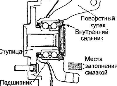
Pic. 14.18. Hub bearing fill points with multipurpose grease
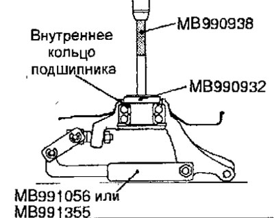
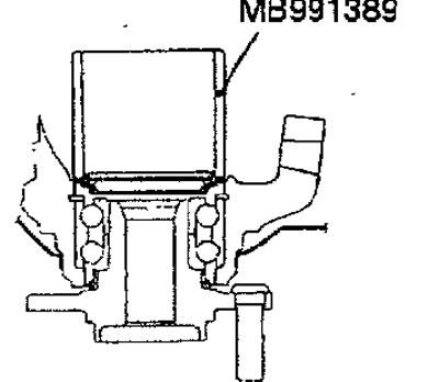
- Using special tools, press the bearing into the steering knuckle (pic. 14.19).
Pic. 14.19. Using special tools to press the bearing into the steering knuckle
Warning. Apply the pressing force to the outer race of the bearing.
- Install retaining ring.
- Install the oil seal with a special mandrel (from the side of the hub) into the steering knuckle flush with the end surface of the steering knuckle (fig 14.20). Apply multipurpose grease to the lip of the seal and to the inside and end surfaces of the seal in contact with the hub.
Pic. 14.20. Using a special mandrel to install the outer oil seal
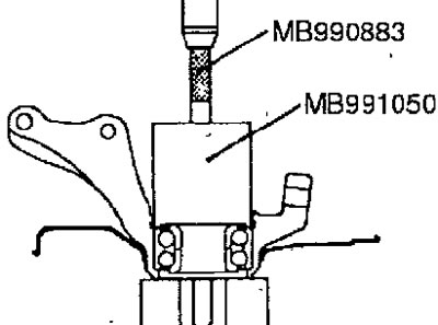
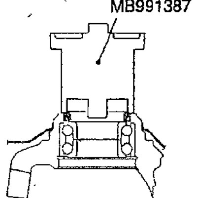
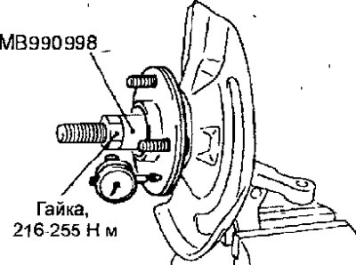
- Install the hub into the steering knuckle using special tools (pic. 14.21).
Pic. 14.21. Using special tools to install the hub in the steering knuckle
- Tighten the special tool nut to 216-255 Nm.
- Turn the sleeve several times to ensure that all bearing elements are correctly installed.
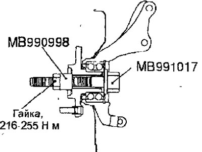
- Fix the steering knuckle in a vise, turn the nut of the special tool with a torque wrench and check the initial torque that must be applied to rotate the hub (pic. 14.22).
Pic. 14.22. Checking the initial torque required to rotate the hub
- The initial torque that must be applied to rotate the hub: no more than 1.8 Nm
- Make sure that the initial torque required to turn the hub is correct and that the bearing turns smoothly and without binding.
- Using an arrow-type indicator, measure the axial play of the front wheel hub (pic. 14.23).
Pic. 14.23. Checking the axial play of the front wheel hub
Axial play of the front wheel hub: no more than 0.05 mm
- If, when tightening the nut with a special tool to a torque of 216-255 Nm, the values of the initial torque that must be applied to rotate the hub and the axial play of the hub bearing are not within the specified limits, then this is probably the result of incorrect installation of the bearing, hub and / or incorrect assembling these parts with a steering knuckle. In this case, it is necessary to replace the bearing and assemble the assembly again.
- Install the inner seal. Apply multipurpose grease to the back of the inner oil seal and use the special tool to install the inner oil seal into the steering knuckle until it contacts the retaining ring (rice) 14.24. Apply a coat of grease to the seal lip.
Pic. 14.24. Using the tool to install the inner oil seal in the steering knuckle