



Contents: Removal ⤓ Installation ⤓
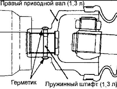
Fig. 14.39. Drive shafts of cars with gasoline engines: 1 - Drive shaft fastening nut, 216-255 Nm; 2 - lower arm ball joint; 3 - Ball joint of the steering rod end; 4 - left drive shaft (car with 1.3 l engine); 5 - spring cylindrical pin (car with 1.3 l engine); 6 - Right drive shaft (car with 1.3L engine); 7 - drive shaft (car with 1.8 l engine); 8- split retaining ring (car with 1.8L engine)
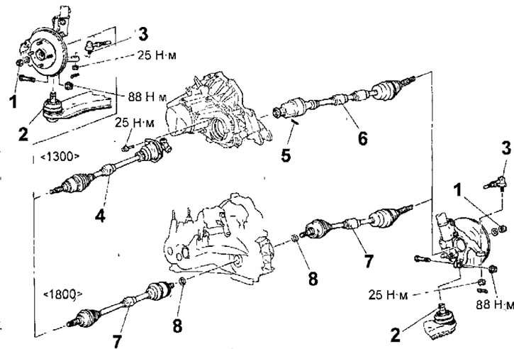
Fig. 14.40. Drive shafts of a vehicle with a diesel engine F9Q1: 1 - drive shaft mounting nut, 216-255 Nm; 2 - lower arm ball joint; 3 - ball joint of the steering rod end; 4 - left drive shaft; 5 - bearing bracket clamp; 6 - intermediate shaft and right drive shaft; 7 - bearing bracket
Removal
Caution: On vehicles with ABS, when removing and installing the drive shaft, be careful not to hit the ABS sensor rotor located on the BJ housing, otherwise it will be damaged.
- Loosen the front wheel lug nut. Apply the parking brake, then raise the front of the vehicle and secure it on jack stands. Remove the appropriate front wheel.
- On a vehicle with an F9Q1 engine, remove the lower engine splash guard.
- On a vehicle with ABS, disconnect the connector, remove the bolt and remove the front wheel speed sensor (see fig. 14.8).
- Loosen the nuts and remove the bolts securing the anti-roll bar to the lower arms.
- Using a special device to prevent the hub from turning, unscrew the drive shaft mounting nut (see fig. 14.9).
Warning: After loosening the nut securing the drive shaft to the front wheel hub, do not place the vehicle on the wheels, otherwise the hub bearing will be damaged.
- Remove the cotter pin and loosen the nut securing the ball joint pin of the tie rod end to the steering knuckle.
Warnings
- Do not unscrew the nut securing the ball joint pin of the tie rod end to the steering knuckle. To avoid damaging the threads on the ball joint pin, use the special tool MB991113 or MB990635.
- To prevent the special tool MB991113 or MB990635 from falling, secure it to the front suspension strut with a cord.
- Install the special tool MB991113 or MB990635 as shown in figure 14.10, making sure that the jaws of the tool are parallel. Rotate the bolt of the special tool to push the ball joint pin of the tie rod end out of the steering knuckle, then loosen the nut and remove the ball joint pin from the steering knuckle.
- Loosen the nut, remove the bolt and the lower arm ball joint pin from the steering knuckle.
- Using a special tool attached to the hub, push the drive shaft out of the front wheel hub (Fig. 14.41).
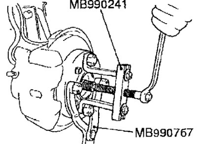
Fig. 14.41. Using a special tool to push the drive shaft out of the front wheel hub
- On a vehicle with a 1.3L engine, remove the bolt (left drive shaft), knock out the split spring cylinder pin (right drive shaft), and remove the drive shaft from the gearbox
- On a vehicle with a 1.8L engine, insert a pry bar between the inner CV joint of the drive shaft and the gearbox and gently tap the pry bar to remove the drive shaft from the gearbox (Fig. 14.42). Use the pry bar very carefully to avoid damaging the joint and the gearbox housing. Do not insert the pry bar too deeply to avoid damaging the differential seal. Do not pull on the drive shaft, as this will damage the constant velocity joints.
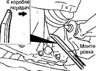
Fig. 14.42. Using a pry bar to remove the drive shaft from the gearbox
Note: When loosening the drive shaft mounting nut, the hub bearing should not be loaded with the eecoih of the vehicle. However, if it is necessary to move the vehicle to another location (the bearing should be loaded with the weight of the vehicle), temporarily tighten the nut with the special tool as shown in Figure 14.43.
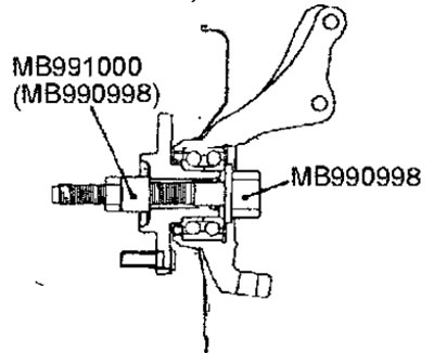
Fig. 14.43. Using special tools for temporary fixation of the hub on the bearing
Installation
- Installation is carried out in the reverse order of removal, taking into account the following.
- After applying multi-purpose grease to the splined portion of the right drive shaft of the 1.3L engine, align the split pin hole on the end of the drive shaft with the split pin hole on the end of the shaft on the transmission side, then install the drive shaft.
- If the split pin hole is slightly misaligned, rotate the right drive shaft 180° and then try installing it again.
Warning: Because the drive shaft has an odd number of splines, the pin hole will be offset by half a diameter if the shaft is rotated 180°.
- Apply MITSUBISHI GENUINE PART MD970389 or equivalent sealant to the split spring pin, and then insert it into the drive shaft.
- After installing the pin, apply MITSUBISHI GENUINE PART MD970389 sealant to both sides of the pin hole to completely seal them (Fig. 14.44).
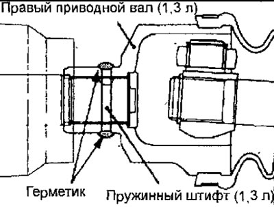
Fig. 14.44. Places where sealant is applied when fastening the right drive shaft to the gearbox on a vehicle with a 1.3 L engine
- Place a washer under the drive shaft to hub mounting nut as shown figure 14.12.
- Using a torque wrench, tighten the drive shaft-to-hub nut to the required torque while using a special tool to prevent the hub from turning.
Warning: Before tightening the drive shaft-to-hub nut, make sure the front wheel hub bearing is not loaded with the weight of the vehicle.
- On a vehicle with ABS, install the front wheel speed sensor, secure it with a bolt and connect the electrical connector.
- Install the anti-roll bar and tighten the self-locking nut so that the anti-roll bar mounting bolt protrudes 22 mm above the nut.