



Warnings
- Do not disassemble the RJ CV joint.
- Be careful not to damage the rotor attached to the outer ring of the RJ CV joint.
Disassembly
- Remove the drive shaft.
- Remove the clamps securing the protective cover (Fig. 14.45).
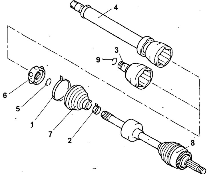
Fig. 14.45. Drive shaft: 1 - large clamp for fastening the protective cover of the TJ CV joint.; 2- small clamp for fastening the protective cover of the TJ CV joint.; 3 - CV joint housing TJ right drive shaft; 4 - CV joint housing TJ left drive shaft; 5 - retaining ring; 6 - hinge assembly; 7 - protective cover for CV joint TJ.; 8 - CV joint RJ.; 9 - left drive shaft retaining ring
- Remove the snap ring from the end of the drive shaft.
- Remove the joint housing from the drive shaft.
- Remove the protective cover of the TJ CV joint. If the cover is to be reinstalled, then before removing the cover, wrap the shaft splines with adhesive tape.
- Clean out old grease from the CV joint.
Examination
- Wash all hinge parts with solvent until the old hinge grease is completely removed.
- Check all hinge parts for cracks, gouges, scoring, pitting and uneven wear.
Assembly
- Wrap the drive shaft splines with tape and slide the new protective boot onto the drive shaft. Remove the tape.
- Fill the constant velocity joint with fresh grease.
- Install the inner joint housing onto the drive shaft.
- Remove excess grease and install the boot onto the CV joint housing, then bleed air from under the boot.
- Using a special tool, secure the protective cover with new clamps. Cut off the protruding tail of the clamp.
- Install the drive shaft.
[The original can be found on the website www.mitsubishiman.ru]