



Contents: Examination ⤓ Installation ⤓
Warnings
- 1. When removing the rear wheel hub, the inner bearing ring may remain on the fastener axis. In this case, replace the rear wheel hub together with the bearing.
- 2. The rear wheel hub bearing unit must not be disassembled. Any damage or even scratches on the teeth of the wheel speed sensor rotor are not allowed. Do not drop the rotor. If a part of the rotor tooth breaks off as a result of rotor deformation, this will lead to the impossibility of correctly determining the wheel speed and disruption of the entire ATZ system.
- Loosen the rear wheel nuts, then raise the rear of the vehicle and support it on jack stands. Remove the corresponding rear wheel.
- On a vehicle with rear drum brakes, remove the screws and brake drum (Fig. 14.53).
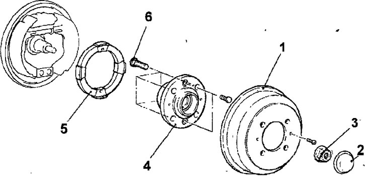
Fig.14.53. Rear wheel hub of a car with rear drum brakes: 1 - brake drum; 2 - cap; 3 - flange nut, 172 Nm; 4 - rear wheel hub; 5,- ABS rotor; 6 - wheel mounting bolt
- On a car with rear disc brakes, unscrew the 2 bolts and remove the caliper assembly. Without disconnecting the soft wire brake hose from the caliper, tie the caliper to the body, but do not stretch or twist the brake hose. Unscrew the 2 bolts and remove the brake disc (Fig. 14.54).
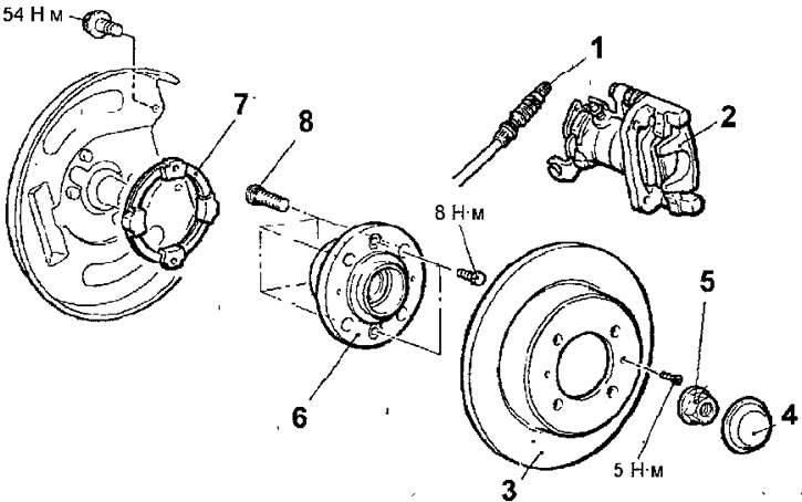
Fig. 14.54. Rear wheel hub of a car with rear disc brakes:1 - parking brake cable; 2 - support; 3 - brake disc; 4 - cap; 5 - flange nut, 172 Nm; 6 - rear wheel hub; 7 — ABS rotor; 8 - wheel mounting bolt
- Use a screwdriver to lever off the cap.
- Loosen the hub mounting nut.
- Remove the rear wheel hub assembly.
- Remove the wheel speed sensor rotor (vehicles with ABS).
[The material was copied from the website mitsubishiman.ru]
Examination
- Check the hub seal for cracks or damage.
- Check the hub bearing for wear or damage.
- Check for chipping of the wheel speed sensor rotor teeth.
Installation
- Installation is carried out in the reverse order of removal, taking into account the following.
- Temporarily install the wheel speed sensor into the sensor bracket.
- Insert the feeler gauge into the gap between the rotor tooth and the pole of the wheel speed sensor, adjust the gap to a value of 0.1-1.9 mm and secure the sensor bracket (Fig. 14.55).
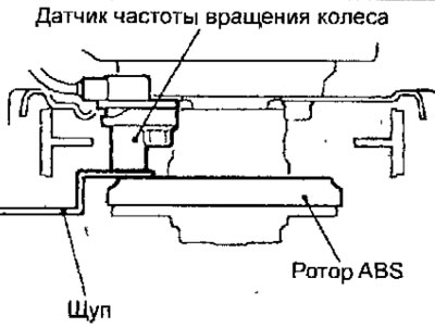
Fig. 14.55. Using a feeler gauge to measure the gap between a rotor tooth and a wheel speed sensor pole
- On a vehicle with rear disc brakes, adjust the parking brake.