
English Русский
Български
Беларускі
Український
Српски
Hrvatski
Română
Polski
Slovenský
Magyar
Articles Bookmark Contacts Sitemap   
Company Audi Company Ford Company Hyundai Company Kia Company Mazda Company Mercedes-Benz Company Nissan
MitsubishiMan.ru


Home Colt Lancer Galant L200 Outlander Pajero Others
Carisma (1995-2004) Space Star (1998-2005)

Repair of the front suspension shock absorber (Mitsubishi Space Star)

  • Home
  • Mitsubishi
  • Space Star (1998-2005)
  • Chassis and running gear
  • Suspension and drive shafts
  • Repair of the front suspension shock absorber
0
Contents: Disassembly ⤓ Shock absorber disposal ⤓ Examination ⤓ Assembly ⤓

Disassembly


  • Secure the front suspension strut and, using a special device with grips, compress the spring so that it moves away from the upper plate (Fig. 14.27).
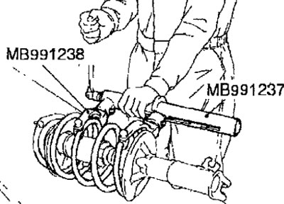


Fig. 14.27. Using a special device to compress the front suspension shock absorber spring


Warnings
  • (1) Install the special devices symmetrically and so that its maximum length does not exceed the installation limits.
  • (2) Do not use an air impact tool to tighten the bolt of the special spring compressor, otherwise the special tool may be damaged.

  • Secure the shock absorber rod with a wrench to prevent it from turning and use a second open-end wrench to loosen the central nut securing the shock absorber rod (Fig. 14.28).
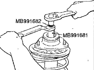


Fig. 14.28. Unscrewing the central nut securing the shock absorber rod


Warning: To avoid loosening the piston rod lock nut, do not use an impact wrench.

  • Remove the shock absorber damping support, upper spring plate and upper spring pad from the shock absorber rod.
  • Remove the spring together with the spring compressor, the rubber compression buffer and the lower spring pad.
  • Loosen the tool bolt until the spring is fully extended and remove the tool from the spring.

Shock absorber disposal


  • Pull the shock absorber rod out completely.
  • To remove gas from the shock absorber cylinder, drill a 3.0 mm diameter hole in the location shown in Figure 14.29.
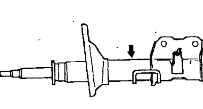


Fig. 14.29. Location of drilling a hole for removing gas from the shock absorber cylinder


Note: The gas escaping from the shock absorber is safe, but care must be taken to avoid injury from flying chips.


Examination


  • Check the strut support bearing for wear or damage.
  • Check rubber parts for damage or deterioration.
  • Check the coil spring for deflection and loss of elasticity.
  • Check the shock absorber as follows:

a. Grasp the shock absorber rod with your hand and push it in and out of the shock absorber several times;

b. Check that the piston rod moves smoothly, without sticking, and that the force applied to the piston rod does not change with each stroke;


c. Make sure that there is no extraneous noise when moving the rod.

Assembly


  • When installing, it is necessary to use springs with the same technical characteristics (with the same color marking) on one axle of the vehicle.
  • Install special tool MB991237 and MB991238 on the new spring and compress it to install it on the shock absorber.

Warning: Do not use an impact wrench to tighten the special tool bolt as this will cause the bolt to lock.

  • Install the compressed coil spring so that its lower end is correctly positioned in the lower spring pad.
  • Install the rubber compression buffer, upper spring plate and strut damper support, then temporarily tighten the shock absorber rod mounting nut.
  • Align the holes in the lower and upper spring support plates. This job is easily accomplished using a length of pipe as shown in Figure 14.30.
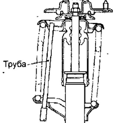


Fig. 14.30. Using a piece of pipe to align the holes in the lower and upper support plates of the strut spring

  • Correctly align both end coils of the spring with the grooves in the upper and lower plates, then loosen and remove the special spring compressor.
  • Use a wrench to prevent the shock absorber rod from turning and use a second open-end wrench to tighten the central nut securing the shock absorber rod to the required torque (see Fig. 14.28).

Warning: To avoid loosening the piston rod lock nut, do not use an impact wrench.


  • Apply general purpose grease to the front strut damper bearing (Fig. 14.31).
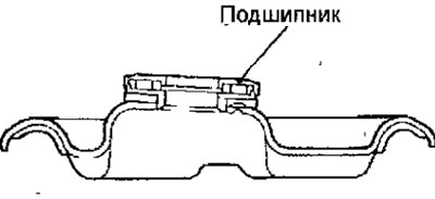


Fig. 14.31. Location of the front strut damper support bearing


Warning: Be careful when applying grease; do not allow grease to come into contact with the rubber elements of the damping support.
This article is available at: russian, bulgarian, belarusian, ukrainian, serbian, croatian, romanian, polish, slovak, hungarian
This article was reviewed by: Miroslav Rakov
Share with friends:
◀ Previous
Space Star: Suspension and drive shafts
Next ▶

Front suspension shock absorber strut
Front wheel hub
Replacing the wheel mounting bolt
Checking the front wheel hub play
Camber, longitudinal and transverse tilt of the steering axis
Lower control arm of the front suspension
Anti-roll bar
Drive shafts
Repair of drive shafts
Rear suspension
Similar materials for other Mitsubishi models

➤ Front shock absorber strut — design description Mitsubishi Colt 5 (1995-2003, petrol)
➤ Disassembling the front strut / removing and installing the… Mitsubishi Lancer 3 and 5 (1984-1992)
➤ Restorative repair of front suspension strut assemblies Mitsubishi Galant 6 and 7 (1987-1998)
➤ Front suspension shock absorber — removal and installation Mitsubishi L200 4 (2005-2014, diesel)
➤ Front Suspension Specifications and Testing Mitsubishi Outlander 1 (2003-2008)
➤ Shock absorber operating mode regulator Mitsubishi Pajero 1 and 2 (1982-1999)
Link in different formats to this article
Comments and feedback from visitors
No comments yet


Add up two numbers 27 + 29


Carisma (1995-2004) 
  • General information
  • User manual
  • Maintenance
  • Power unit
  • Petrol engines 4G9
  • Diesel engines FBQT
  • Diesel engines F9Q
  • Cooling system
  • Injection system (MPI)
  • Injection system (GDI)
  • Engine electrical equipment
  • Transmission
  • Clutch
  • Mechanical gearbox
  • Automatic gearbox
  • Chassis and running gear
  • Steering
  • Brake system
  • Front suspension and shafts
  • Rear suspension
  • Body and interior
  • Exterior (external elements)
  • Interior (internal elements)
  • Doors, locks and windows
  • Air conditioner
  • Electrical equipment
  • Equipment and devices
  • Headlights and lighting
  • Electrical circuits
Space Star (1998-2005) 
  • General information
  • User manual
  • Maintenance
  • Power unit
  • Petrol engines 4G9
  • Petrol engines 4G1
  • Diesel engines F9Q1
  • Cooling system
  • Fuel injection system GDI
  • Fuel injection system MPI
  • Diesel supply system F9Q1
  • Ignition system
  • Diesel preheating
  • Transmission
  • Clutch
  • Mechanical gearbox
  • Automatic gearbox
  • Chassis and running gear
  • Suspension and drive shafts
  • Brake system
  • Steering
  • Body and interior
  • Exterior (external elements)
  • Interior (internal elements)
  • Doors, locks and windows
  • Heating and air conditioning
  • Electrical equipment
  • Power devices
  • Equipment and devices
MitsubishiMan.ru © 2018–2026 • Mobile version • Articles about Mitsubishi • Contacts • Sitemap: EN BG BY UA RS HR RO PL SK HU • Site search • Bookmark
Colt 2 and 3 (1983-1993) · Colt 4 and 5 (1991-2003) · Colt 5 (1995-2003) · Lancer 3 and 5 (1984-1992) · Lancer 9 (2000-2007) · Galant 5 (1983-1989) · Galant 6 and 7 (1987-1998) · L200 4 (2005-2014) · Outlander 1 (2003-2008) · Pajero 1 and 2 (1982-1999) · Pajero 4 (2006-2021) · Carisma (1995-2004) · Space Star (1998-2005) ·
This resource sets cookies 🍪 to avoid bothering you with repeated data entry.