
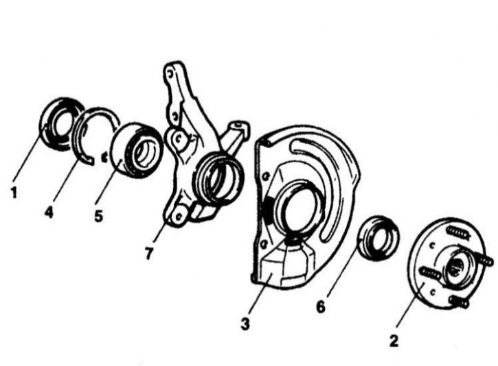
The design of the hub assembly of the front wheel of the Mirage and Diamante models
1 - Internal gland; 2 - Hub; 3 - Dust screen; 4 - Retaining ring; 5 - Wheel bearing; 6 - Outer gland; 7 - Swivel fist
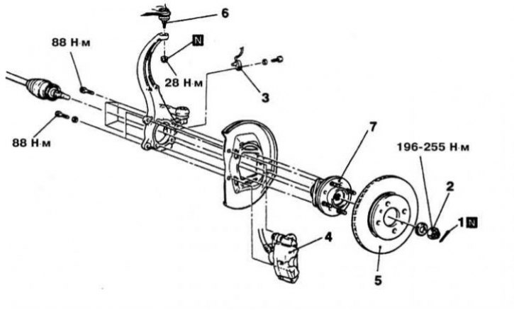
Design of hub assembly for Galant models 1994÷1998. issue
1 - Cotter pin; 2 - Hub nut; 3 - Wheel sensor (models with ABS); 4 - Brake caliper; 5 - Brake disc; 6 - Upper ball joint; 7 - Hub Assembly
Models Diamante, Mirage and Galant up to 1993 and since 1999 issue
Removing
1. The design of the hub assembly of the front wheel of the models under consideration is shown in the illustration.
2. Disconnect the negative cable from the battery.
Attention! If the stereo system installed in the car is equipped with a security code, before disconnecting the battery, make sure that you have the correct combination to activate the audio system!
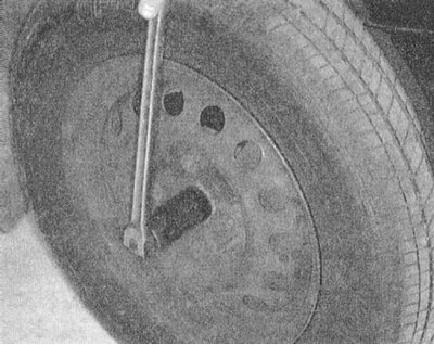
3. Jack up the car and put it on stands. Remove the respective front wheel and give the hub nut.
4. On models equipped with ABS, remove the wheel sensor.
5. On models with active suspension (Active-ECS) Disconnect the ride height sensor from the lower control arm.
6. Remove the caliper and brake pads. Tie the caliper to the suspension elements, trying not to allow tension on the brake hose.
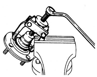
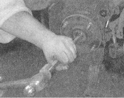
7. Using a special puller, release the ball joint and the tie rod end from the steering knuckle assembly.
8. Release the drive shaft from the hub.
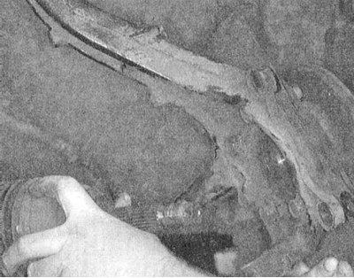
9. Bolt off the bottom end of a rack and remove a nave in gathering with a rotary fist from the car.
10. Transfer the removed assembly to the workbench.
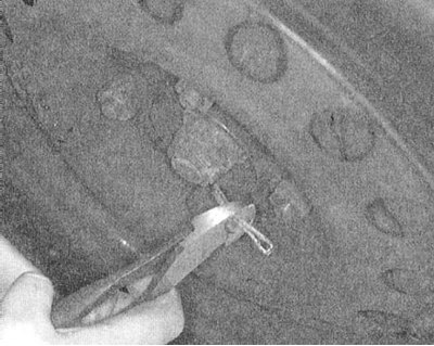
11. Prying with a small screwdriver with a blunted hall, remove the oil seal from its seat, installed on the side of the steering knuckle facing the drive shaft.
12. Using a puller, separate the hub from the steering knuckle.
13. Using a puller, remove the wheel bearing inner race from the hub.
Attention! In order to avoid damage to the bearing, in no case knock out the cage from the hub with a hammer! Take care that the hub does not fall when removing the cage.
14. Remove the lock ring installed from the party of a rotary fist turned towards a power shaft. Using a puller, release the bearing from the knuckle assembly.
15. After the bearing has been removed, its outer race can be knocked out with a brass drift.
Installation
1. Pack the wheel bearing with multipurpose grease. Lubricate the bearing surfaces of the steering knuckle with a thin layer of the same grease.
2. Press the bearing into the knuckle, then use the special tool to install the bearing inner race.
3. Using a suitable drift, drive the inner seal into its seat, flush with the end face of the knuckle.
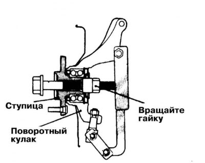
4. With the help of a special device of the MB990998 type, fit the hub into a fist, - the nut of the fitting tool is tightened with a force of 200÷260 Nm. Rotate the hub to shrink the bearing.
5. Clamp the fist in a vice with soft jaws and use the nozzle MB990998 and a torque wrench to measure the torque of the hub. The maximum allowable value is 1.8 Nm. Check the freedom of rotation of the bearing.
6. Install the dial gauge so that its plunger rests against the machined end surface of the hub and determine the amount of axial play of the assembly. The maximum allowable value is 0.05 mm.
7. If, when tightened with the required force (200÷260 Nm) hub nut, the axial play or turning torque exceeds its maximum allowable values, therefore, there is a violation when installing the bearing or knuckle - repeat the assembly procedure.
8. Establish assembly of a nave with a fist on the regular place on the car. Insert the ball joint pin into the knuckle and tighten its new nut to the required torque (72 Nm).
9. Insert the drive shaft into the hub.
10. Connect the rack and tighten the bolts of its fastening with the required force (110÷130 Nm: for Mirage models and 90÷105 Nm: for Diamante models).
11. Place the tie rod end in the fist and tighten the nut of its ball pin with the required force (34 Nm: for Mirage models and 29 Nm: for Diamante models).
12. Install the brake disc and caliper.
13. On models with active suspension (Active-ECS) Install the ride height sensor and tighten its fastening bolt to 20 Nm.
14. On models with ABS, reinstall the wheel sensor (see chapter Brake system).
15. Install the washer, screw a new locknut onto the drive shaft trunnion and tighten it to the required torque (200÷260 Nm).
16. Install the wheel and lower the vehicle to the ground.
Galant models 1994÷1998 issue
Removing
Attention! Front wheel hub assembly on Galant models 1994÷1998. issue disassembly and maintenance is not subject!
1. The design of the hub assembly on Galant models 1994÷1998. issue shown in the illustration.
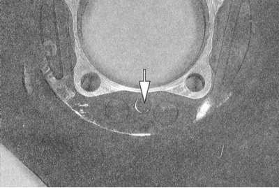
2. Remove the cotter pin, give the hub nut and remove the washer.
 |  |
3. Jack up the car and put it on stands. Remove the corresponding front wheel.
4. On ABS-equipped models, remove the wheel sensor.
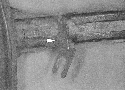
5. Remove the caliper and brake pads. Remove the retainer and release the brake hose from the bracket to the steering knuckle assembly. Tie the caliper to the suspension elements, making sure that the brake hose is not stretched.
6. Remove the brake disc from the hub assembly.
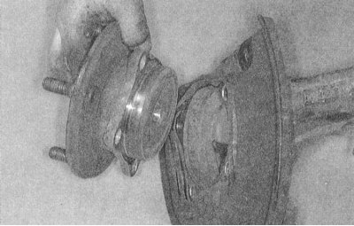
7. Release the upper ball joint from the steering knuckle and pull the assembly of the latter outward, releasing the drive shaft from it.
 |  |
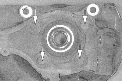 |
8. From the back side of a rotary fist turn out four bolts of fastening of a nave.
9. Remove the hub assembly with the wheel bearing - the hub cannot be repaired and must be replaced in case of failure.
Installation
1. If the steering knuckle needs to be replaced, transfer the brake dust shield and hydraulic hose support bracket to the new assembly
 |  |
2. Install the hub on the steering knuckle assembly and tighten the bolts of its fastening with the required force (88 Nm).
3. Insert the upper ball joint into the knuckle and tighten the ball stud self-locking nut to the required torque (28 Nm).
4. Install washer and torque to specification (200÷260 Nm) hub nut.
5. Install the brake disc on the hub assembly.
6. Install anchor bracket and brake caliper.
7. On models with ABS, install the wheel sensor.
8. Install the wheel and lower the vehicle to the ground.