



Galant models up to 1993.
Removal
1. Disconnect the negative cable from the battery.
Warning! If the car stereo system is equipped with a security code, make sure you have the correct combination to activate the audio system before disconnecting the battery!
2. Jack up the car and place it on supports.
3. Remove the stabilizer bar struts or the bolts that secure it to the lower control arm. If so equipped, remove the support cups/bushings.
4. Using a special puller type MB9f35, release the ball joint pin from the hub assembly knuckle - if the support is to be used further, proceed with extreme caution.
5. Remove the inner bolts and nut securing the lower suspension arm.
6. Unscrew the rear bolts and, if equipped, remove the mounting clamp.
7. Remove the lever from the vehicle.
8. If necessary, remove the bushing from the rear rod.
Installation
1. If removed, install the bushing on the lever.
2. Place the lever assembly in its original place and secure it with the internal bolts. Screw on and temporarily tighten the new nut.
3. Install the rear mounting clamp, screw in the bolts. Tighten the new clamp mounting nuts to the required torque (47 Nm), temporarily tighten the clamp bolt, - the final tightening of the bolt to the required torque (100 Nm) is performed after lowering the car to the ground.
4. Press the ball joint into the hub assembly knuckle and secure it with a new nut, tightening the latter to 60÷72 N·m.
5. Install the anti-roll bar with its struts.
6. Lower the vehicle to the ground and tighten the nuts of the inner arm mounting bolts to a final torque of 120 Nm (100 Nm) for the clamp bolt.
7. Make sure that the suspension element fasteners are securely tightened.
8. Connect the negative cable to the battery.
Galant models since 1994.
Lower control arm
Removal
1. Jack up the car and place it on stands. Remove the corresponding rear wheel.
2. On ABS models, remove the wheel sensor wiring support brackets from the lower control arm assembly.
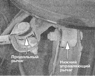
3. Remove the through bolt securing the lower hub assembly knuckle to the control arm.
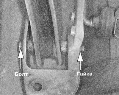
4. Remove the bolt securing the lower control arm to the suspension beam.
5. Remove the lever from the vehicle.
Installation
1. Connect the control arm to the suspension beam and temporarily tighten the mounting bolt nut.
2. Connect the lever to the hub assembly knuckle, - also temporarily tighten the through bolt nut.
3. Connect the anti-roll bar to the control arm. Tighten the mounting nut to the required torque (39 N·m).
4. Install the wheel and lower the car to the ground.
5. Perform final tightening of the nuts of both mounting bolts to the required torque (98 Nm).
6. Check the rear wheel alignment angles and make appropriate adjustments if necessary.
Lower toe-in control lever
Removal
Note: The ball joint is built into the lever assembly and, if it fails, is replaced together with the latter.
1. Jack up the car and place it on stands. Remove the corresponding rear wheel.
2. Mark the position of the adjusting bolt.
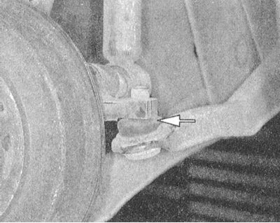
3. Using a puller type MB991113, release the ball joint pin from the hub assembly knuckle.
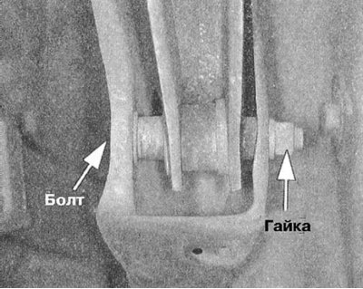
4. Loosen the bolts securing the arm to the suspension beam and remove the arm assembly from the vehicle.
Installation
1. Connect the arm to the suspension beam, align the adjustment bolt alignment marks, then temporarily tighten the mounting bolt nut.
2. Press the ball joint pin into the hub assembly knuckle and tighten the fastening nut to the required torque (28 Nm).
3. Install the wheel and lower the car to the ground.
4. Finally tighten the bolt pair securing the control arm to the suspension beam to the required torque (69÷78 Nm)
5. Check the rear wheel alignment angles and make appropriate adjustments if necessary.
Diamante Models
Removal
1. Jack up the car and place it on stands. Remove the corresponding rear wheel.
Information copied from the website www.mitsubishiman.ru
2. Mark the position of the adjusting bolt.
3. On models with active suspension (Active-ECS) disconnect the ride height sensor rod from the lower arm assembly.
4. Support the trailing arm with a jack and loosen the self-locking nut securing the lower arm to the trailing arm.
5. Disconnect the control arm assembly from the suspension beam and remove it from the vehicle.
Installation
1. Connect the arm to the suspension beam, align the adjustment bolt alignment marks, then temporarily tighten the mounting bolt nut.
2. Connect the assembly to the longitudinal arm and tighten the self-locking nut to the required torque (75÷89 Nm).
3. On models with active suspension, connect the ride height sensor rod to the lever.
4. Install the wheel and lower the car to the ground.
5. Finally tighten the bolt pair securing the control arm to the suspension beam with the required torque (75÷89 Nm)
6. Check the rear wheel alignment angles and make appropriate adjustments if necessary.