



Contents: Removal the lower wishbone assembly ⤓ Installing the rear lower control…⤓ Checking the tightening torque of…⤓ Checking the protective boot of the…⤓ Replacing the protective cover of…⤓
Removal the lower wishbone assembly
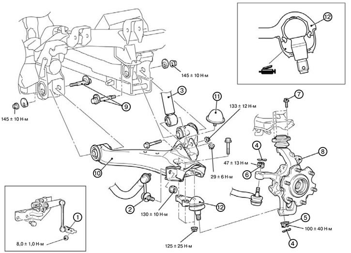
1. Remove the front suspension height sensor and upper arm connection (1).
2. Disconnect the lower arm and stabilizer bar connection (2).
3. Disconnect the shock absorber and lower suspension arm connection (3).
4. Remove the cotter pin (4).
5. Disconnect the rear lower arm and steering knuckle connection (5).
Caution: Use a special tool to loosen the nut. The nut should be loosened, but not completely removed. To prevent the puller from slipping off, it is necessary to first tie it with a cord or wire.
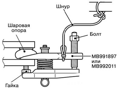
6. Disconnect the connection between the steering rod end and the steering knuckle (6).
7. Disconnect the connection of the upper arm and the upper arm ball joint (7).
8. Remove the hub and steering knuckle assembly (8).
9. Loosen the lower suspension arm mounting bolt (9).
10. Remove the lower suspension arm (10).
11. Remove the limiter (11).
12. Remove the lower suspension arm ball joint (12).
Installing the rear lower control arm and lower wishbone assembly
Caution: * Indicates parts that must be pre-tightened and then finally tightened with the unloaded vehicle on its wheels on a level, horizontal surface.
Note: When installing, tighten the bolts to the torques shown in the figure.
1. Install the lower suspension arm ball joint (12).
2. Install the limiter (11).
3. Install the lower suspension arm (10).
4. Tighten the lower suspension arm mounting bolt (9).
5. Install the hub and steering knuckle assembly (8).
6. Connect the upper arm joint and the upper arm ball joint (7).
7. Connect the tie rod end and steering knuckle joint (6).
8. Connect the rear lower arm and steering knuckle joint (5).
9. Install the cotter pin (4).
10. Connect the shock absorber and lower suspension arm joint (3).
11. Connect the lower arm and stabilizer bar joint (2).
12. Install the front suspension height sensor and upper arm connection (1).
Checking the tightening torque of the ball joint of the rear wishbone
1. Rock the ball joint pin several times, install the nut on the pin and, using a special tool, measure the moment the ball joint starts to rotate.
Rear lower arm ball joint:
- Nominal value: 1.0 - 6.9 Nm
Lower wishbone ball joint:
- Nominal value: 1.5 N·m or less
2. If the measured value exceeds the standard value, replace the lower arm assembly.
3. If the measured value is less than the nominal value, check the ease of movement of the pin in the ball joint. If the pin does not stick and there is no excessive play, then using such a ball joint (ball joint) allowed.
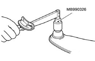
Checking the protective boot of the ball joint of the lower wishbone
1. Check the protective cover for cracks or damage by pressing on it with your finger.
2. If the protective boot is cracked or damaged, replace the lower control arm assembly.
Note: Cracks or damage to the protective boot may cause damage to the ball joint. If the protective cover is damaged during maintenance work, replace the protective cover.
Replacing the protective cover of the ball joint of the lower wishbone suspension
Replace the ball joint protective boot only if it is accidentally damaged during maintenance work, as follows:
1. Remove the protective cover.
2. Apply multi-purpose grease to the inside of the protective boot.
3. Apply multi-purpose grease to the indicated location on top of the lower control arm assembly boot.
Caution: Be careful not to allow multi-purpose grease to come into contact with the threads and cone portion of the ball joint pin. If this happens, wipe off the grease.
4. Put on the protective cover using the special tool until it fits into place.
5. Check the protective cover for cracks and damage by pressing on it with your finger.