



Contents: Diamante Models ⤓ Galant models up to 1993, FWD ⤓ Galant models up to 1993, AWD ⤓ Galant models since 1994. ⤓ Mirage Models ⤓
Diamante Models
Removal
1. Disconnect the negative cable from the battery.
Warning! If the car stereo system is equipped with a security code, make sure you have the correct combination to activate the audio system before disconnecting the battery!
2. Jack up the car and place it on stands. Remove both rear wheels.
3. Support the lower suspension arm with a jack.
4. Mark the installation position of the upper plate of the coil spring.
5. On models with active suspension (Active-ECS) loosen the nut securing the air line to the top of the rack. Discard the sealing ring - it must be replaced without fail. Unscrew the mounting bolts and remove the Active-ECS actuator from the top of the rack - do not forget to disconnect the electrical wiring.
6. Unscrew the bolt of the lower shock absorber support. Loosen the nuts securing the upper shock absorber plate to the body element.
7. Lower the jack supporting the lower arm, remove the strut and take it out from under the car.
Installation
1. Insert the upper plate of the coil spring into its regular place and install the rack on the car, - use a jack.
2. Tighten the upper mounting nuts to the required torque (45 Nm).
3. Tighten the lower bolt to 98 N·m.
4. On Active-ECS models, connect the air line to the strut - do not forget to replace the sealing ring. Tighten the union nut to the required torque (9 Nm).
5. Install the Active-ECS actuator on the rack, connect the electrical wiring to it and secure it with bolts.
6. Remove the jack, install the wheels and lower the car to the ground.
7. Connect the negative cable to the battery.
Galant models up to 1993, FWD
Removal
Note: Since the strut is the component that determines the load on the wheel bearing, the chassis and rear axle of the vehicle must be supported separately with different jacks.
1. Disconnect the negative cable from the battery.
Warning! If the car stereo system is equipped with a security code, make sure you have the correct combination to activate the audio system before disconnecting the battery!
2. Jack up the car and place it on supports.
3. Lightly support the torsion beam and lever - make sure that the jack does not touch the transverse reaction rod.
Attention! It is necessary to place a wooden block between the jack head and the bridge beam, and place the jack under the central part of the beam.
4. To gain access to the upper mounting nuts, remove the corresponding luggage compartment trim elements.
5. On models with active suspension (Active-ECS) label and disconnect the air lines from the top of the shock absorber. Immediately plug the open ends of the tubes and fittings to prevent dirt from entering the system. Try to avoid twisting or kinking the tubes. Remove the sealing ring and bushing. Remove the actuator assembly.
6. Remove the protective cover and loosen the upper shock absorber mounting nuts.
7. Remove the lower mounting bolt and remove the strut assembly from the vehicle.
Installation
1. Place the rack in its regular place, screw in and lightly tighten the lower mounting bolt.
2. Jack up the rear axle beam until the mounting studs of the upper shock absorber support fit into the receiving holes. Fix the stand in the upper position.
3. Screw the fastening nuts onto the studs and tighten them to the required torque (40 Nm).
4. Lower the vehicle to the ground and finally tighten the lower shock absorber mounting bolt to the required torque (100 Nm).
5. On models with active suspension, reinstall the Active-ECS components and restore the original air line connections - remember to replace the O-rings. Tighten the lock nut to 9 N·m. Wet the nipple connector with soapy water, start the engine and check the connection for signs of air leaks. Replace the O-ring if necessary.
6. Install the upper shock absorber protective cover and luggage compartment trim elements.
Galant models up to 1993, AWD
Removal
1. Disconnect the negative cable from the battery.
Warning! If the car stereo system is equipped with a security code, make sure you have the correct combination to activate the audio system before disconnecting the battery!
2. Jack up the car and place it on supports.
3. Lightly support the trailing arm with a jack.
4. To gain access to the upper mounting nuts, remove the corresponding luggage compartment trim elements.
5. Remove the protective cover and loosen the upper shock absorber mounting nuts.
6. Loosen the brake hose support bracket mounting bolt.
7. Remove the lower mounting bolt and remove the strut assembly from the vehicle.
Installation
1. Place the rack in its regular place, screw in and lightly tighten the lower mounting bolt.
2. Jack up the trailing arm until the mounting studs of the upper shock absorber support fit into the receiving holes. Fix the stand in the upper position.
3. Screw the fastening nuts onto the studs and tighten them to the required torque (40 Nm).
4. Lower the vehicle to the ground and finally tighten the lower shock absorber mounting bolt to the required torque (90÷110 Nm).
5. Install the brake hose support bracket and tighten its mounting bolt to the required torque (17 N·m).
6. Install the upper shock absorber protective cover and luggage compartment trim elements.
Galant models since 1994.
Removal
1. Jack up the car and place it on supports.
The original material is here: MitsubishiMan
2. Lightly support the lower control arm of the suspension with a jack.
3. To gain access to the upper mounting nuts, pull the rear seat stop outward, lift and remove the cushion. Remove the mounting bolts and remove the seat back.
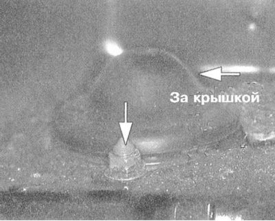
4. Remove the upper shock absorber mounting nuts.
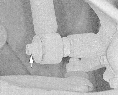
5. Remove the lower mounting bolt and remove the strut assembly from the vehicle.
Installation
1. Place the rack in its regular place, screw in and lightly tighten the lower mounting bolt.
2. Jack up the rear axle beam until the mounting studs of the upper shock absorber support fit into the receiving holes. Fix the stand in the upper position.
3. Screw the nuts onto the studs and tighten them to the required torque (44 Nm).
4. Lower the vehicle to the ground and finally tighten the lower shock absorber mounting bolt to the required torque (98 N·m).
5. Reinstall the rear seat components.
Mirage Models
Removal
1. To gain access to the upper mounting nuts, remove the corresponding luggage compartment trim elements.
2. Remove the protective cover and loosen the upper shock absorber mounting nuts.
3. Jack up the car and place it on supports.
4. Lightly support the trailing arm with a jack.
5. Mark the installation position of the upper spring plate relative to the chassis, then loosen the mounting nuts.
6. Remove the lower mounting bolt and remove the strut assembly from the vehicle.
Installation
1. Place the rack in its regular place, screw in and lightly tighten the lower mounting bolt.
2. Jack up the trailing arm until the mounting studs of the upper shock absorber support fit into the receiving holes. Fix the stand in the upper position.
3. Screw the fastening nuts onto the studs and tighten them to the required torque (27 Nm).
4. Lower the vehicle to the ground and finally tighten the lower shock absorber mounting bolt to the required torque (90 Nm).
5. Install the brake hose support bracket and tighten its mounting bolt to the required torque (17 N·m).
6. Install the upper shock absorber protective cover and luggage compartment trim elements.