
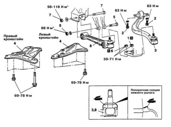
Installation details of lower front suspension arms on Galant models 1994÷1998. issue
1 - Nut for fastening the ball joint of the reactive section of the lower arm in the steering knuckle; 2 - Bolt for fastening the reactive section of the lower arm; 3 - Assembly of the reactive section of the lower suspension arm; 4 - Brackets; 5 - Fasteners for the lower support of the shock absorber; 6 - Nut for fastening the ball joint of the transverse section of the lower arm in the steering knuckle; 7 - Fasteners of the transverse section of the lower suspension arm; 8 - Assembly of the transverse section of the lower suspension arm
* An asterisk marks fasteners, the final tightening of which must be carried out after lowering the vehicle to the ground
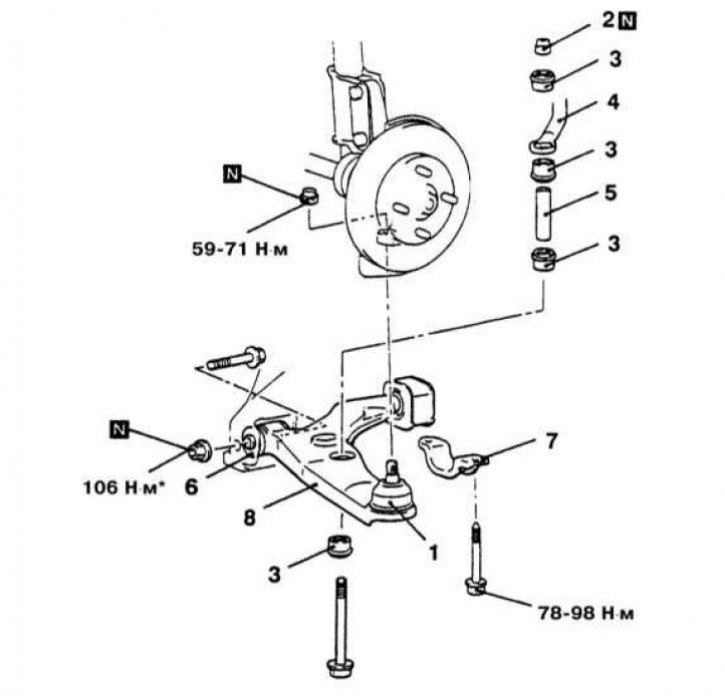
Installation details of the lower suspension arm on Mirage models
1 - Lower ball joint; 2 - Self-locking nut; 3 - Rubber bushing of the anti-roll bar support; 4 - Bar stabilizer bar; 5 - Metal sleeve; 6 - Fasteners of the front support of the lower arm; 7 - Clamp; 8 - Assembling the lower arm
* An asterisk marks fasteners, the final tightening of which must be carried out after lowering the vehicle to the ground
Diamante and Galant models up to 1993 and since 1999 issue
Removing
1. Disconnect the negative cable from the battery.
Attention! If the stereo system installed in the car is equipped with a security code, before disconnecting the battery, make sure that you have the correct combination to activate the audio system!
2. Jack up the car and place it on jack stands so that the wheels are completely off the ground.
3. Disconnect the anti-roll bar from the lower arm.
4. Release the lower ball joint pin from the steering knuckle assembly.
5. Give a fixing nut and take a through bolt of fastening of an internal support of the lever to a frame.
6. Turn out back fixing bolts, at the corresponding complete set remove a collar.
7. If necessary, remove the rear stem bushing.
Installation
1. If removed, install the rear stem bushing to the lower arm assembly.
2. Install the arm assembly to the vehicle and temporarily tighten the through bolt nut.
3. Install the clamp, bolts and replaceable nuts of the rear support. Tighten the bolts with a force of 100÷120 Nm, nuts - 40 Nm.
4. Insert the ball joint pin into the steering knuckle assembly and tighten the new fixing nut to the required torque (60÷72 Nm).
5. Connect to the lever a rack of the stabilizer of cross-section stability.
6. Lower the vehicle to the ground to finish tightening the fasteners.
7. After the entire mass of the car has been transferred to the suspension, tighten the nuts through the bolts of the lower suspension arms with the required force (102÷122 Nm).
8. Connect the negative cable to the battery.
9. Check and adjust the front wheel alignment.
Galant models 1994÷1998 issue
Removing
1. Installation details of lower suspension arms on Galant models 1994÷1998. issue shown in the accompanying illustration. Both ball bearings are mounted in the bodies of their sections of the lower arm and, in the event of their failure, must be replaced as an assembly with the latter.
2. Jack up the car and put it on stands.
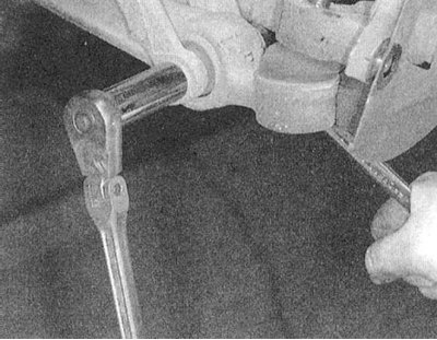
3. Give a nut of a bolt of fastening to cross section of the lower arm of a damper fork of the shock-absorber, take a bolt. Release the lower ball joint pins from the steering knuckle.
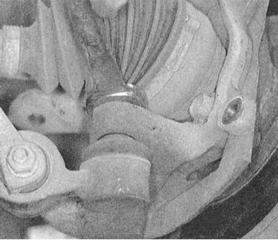
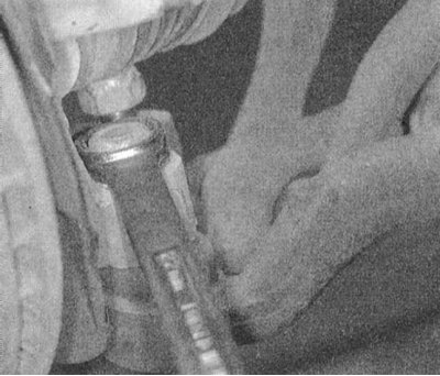 |  |
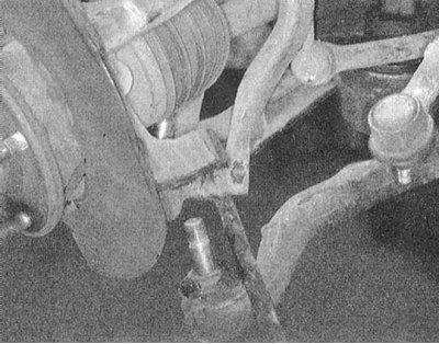 |  |
4. To remove the transverse section of the lever, you must first dismantle the brackets of the lower beam.
5. Give fixture of the internal end of cross section of the bottom lever and remove assembly of the last from the car.
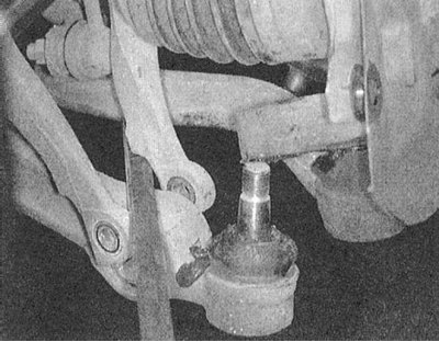
6. Turn out two fixing bolts and remove reactive section of the bottom lever.
Installation
1. Fit the rubber bushings into the lower arm section assemblies.
2. Install the transverse section of the lower suspension arm in its original place. Thread the inner mounting bolt and temporarily tighten the new inner mounting nut.
3. Install the reaction arm section.
4. Fill fingers of both spherical support in assembly of a rotary fist. Screw on new fixing nuts and tighten them to the required torque (59÷71 Nm).
5. Lower the vehicle to the ground and finally tighten the appropriate cross section fasteners to the required torque (98÷118 Nm: inner bolt and 88 Nm: damper fork mounting bolt).
6. With the required force (83 Nm) tighten the reaction section fastening bolts.
7. Reinstall the brackets of the lower beam and tighten the bolts of their fastening with a force of 69÷78 Nm.
8. Adjust the front wheel alignment angles.
Mirage Models
Removing
1. Installation details of the lower control arm assembly on Mirage models are shown in the illustration.
2. Jack up the car and put it on stands. Remove the corresponding front wheel.
3. Remove from assembly of the lower arm of a suspension bracket of a rack of the stabilizer of cross-section stability, or give nuts and take fixing bolts. Remove the cups and bushings of the connecting nodes.
4. Release the ball joint pin from the steering knuckle.
5. Give a nut and take an internal bolt of fastening of assembly of the bottom lever.
6. Turn out bolts of a back fixing collar and remove assembly of the bottom support from the car.
Installation
1. Install the lower arm assembly in its proper place and tighten the nut of the inner mounting bolt to the required torque (108 Nm).
2. Install the rear mounting collar and tighten the bolts of its fastening with a force of 90 Nm.
3. Thread the ball joint pin into the steering knuckle assembly. Screw on a new nut and tighten it with a force of 60÷72 Nm.
4. Attach the anti-roll bar to the arm assembly.
5. Lower the vehicle to the ground and finally tighten the fasteners to the required torque.
6. Install the wheel.