
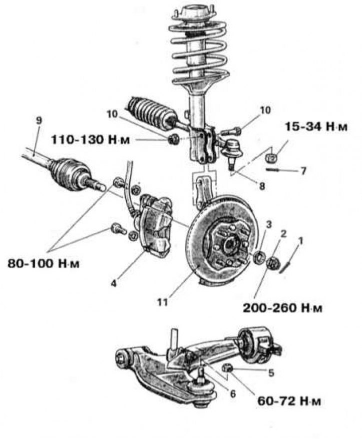
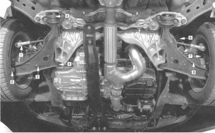
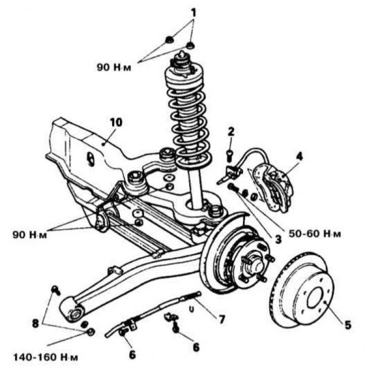
Layout of front suspension components on Mirage models through 1992 issue and Diamante models
1 - Cotter pin; 2 - Drive shaft; 3 - Washer; 4 - Brake caliper; 5 - Self-locking nut; 6 - Finger of the ball joint of the lower suspension arm; 7 - Cotter pin; 8 - Ball pin of the tie rod end; 9 - Drive shaft; 10 - Bolt of the lower support of the rack; 11 - Assembling the hub with the steering knuckle
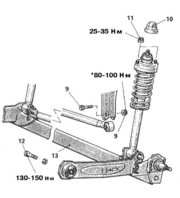
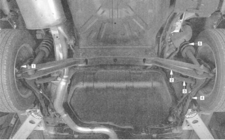
Rear suspension design for Mirage models up to 1992, no.
9 - Bolted pair of fastening of the transverse jet rod; 10 - Protective cover; 11 - Upper shock absorber mounting nut (2 pcs); 12 - Bolt of fastening of the longitudinal suspension arm; 13 - Rear axle beam
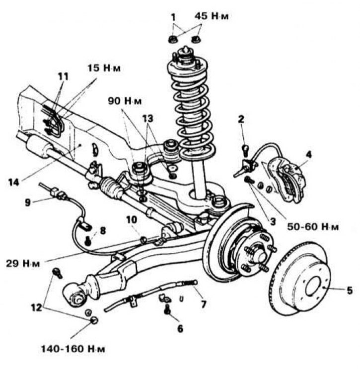
The layout of the front suspension components on Mirage models from 1993 vol.
1 - Tie rod end; 2 - Lower ball joint; 3 - Lower control lever; 4 - Support of the lower control lever; 5 - Bar stabilizer bar; 6 - Anti-roll bar; 7 - suspension strut; 8 - Assembling the hub with wheel bearing; 9 - Drive shaft
Layout of front suspension components on Galant models 1994÷1998. issue
1 - suspension strut; 2 - Swivel fist; 3 - Assembling the hub with wheel bearing; 4 - Lower ball bearings; 5 - Reactive section of the lower control arm; 6 - Transverse section of the lower control arm; 7 - Supports for sections of the lower control arm; 8 - Rack and pinion of the steering drive; 9 - Bar stabilizer bar; 10 - Drive shaft; 11 - Upper ball joint; 12 - Upper control arm
Layout of front suspension components on Galant models since 1999 issue
1 - Tie rod end; 2 - Lower ball joint; 3 - Lower control lever; 4 - Support of the lower control lever; 5 - Bar stabilizer bar; 6 - suspension strut; 7 - Assembling the hub with wheel bearing; 8 - Drive shaft
The design of the rear suspension of Mirage models since 1993, no.
1 - Hub assembly; 2 - Lower control lever; 3 - Control rod; 4 - Longitudinal suspension arm; 5 - Rack Assembly
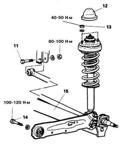
Rear suspension design for Galant models up to 1993, no.
11 - Bolted pair of fastening of the transverse jet rod; 12 - Protective cover; 13 - Upper shock absorber mounting nut (2 pcs); 14 - Bolt of fastening of the longitudinal suspension arm; 15 - Rear axle beam
The design of the rear suspension of Galant models 1994÷1998, vol.
1 - Longitudinal suspension arm; 2 - Lower control lever; 3 - Camber adjustment control lever; 4 - Rack; 5 - Hub Assembly
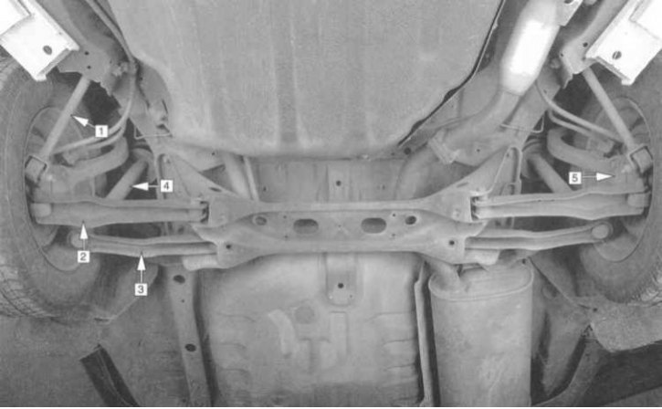
Rear suspension design for Diamante models 1992÷1996 issue without 4WS
1 - Upper shock absorber mounting nuts; 2 - Bolt; 3 - Brake caliper mounting bolts; 4 - Assembling the brake caliper; 5 - Brake disc; 6 - Bolt; 7 - Tip of the parking brake cable; 8 - Bolted pair of fastening of the longitudinal suspension arm; 9 - Beam fastening bolts; 10 - Rear axle beam
The design of the rear suspension of Galant models since 1999, no.
1 - Longitudinal suspension arm; 2 - Hub assembly; 3 - Lower control suspension arm; 4 - Rack assembly; 5 - Anti-roll bar; 6 - Stabilizer bar; 7 - Swivel fist; 8 - Camber adjustment control lever
Rear suspension design for Diamante models 1992÷1996 issue with 4WS
1 - Upper shock absorber mounting nuts; 2 - Bolt; 3 - Brake caliper mounting bolts; 4 - Assembling the brake caliper; 5 - Brake disc; 6 - Bolt; 7 - Tip of the parking brake cable; 8 - Bolt (models with ABS); 9 - Union connector; 10 - Tie rod end nut; 11 - Fitting connectors for hydraulic pipes of the steering gear; 12 - Bolted pair of fastening of the longitudinal suspension arm; 13 - Beam fastening nut; 14 - Rear axle beam
The design of the rear suspension of Diamante models since 1997, no.
Note. Since the maintenance procedures for the suspension components are performed under the vehicle, care should be taken in advance to raise the vehicle and fix it in a raised position (prepare a reliable jack and props).
Attention! Under no circumstances should you carry out any work under the vehicle, which has only been secured in the raised position with a jack!
Front suspension
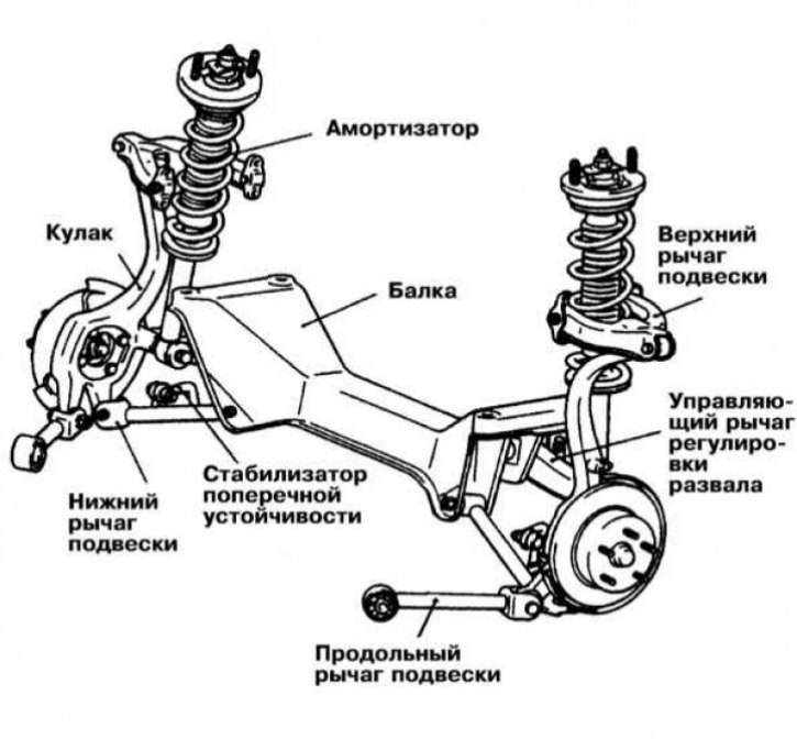
The front suspension on all models is independent. The steering knuckles are connected to the control arms of the suspension by means of ball bearings. Opposite ends of the levers are bolted to the frame. The standard equipment includes an anti-roll bar, which reduces the sway and roll of the car when cornering.
The basis of the front suspension on most models is MacPherson struts, consisting of telescopic shock absorbers and coil springs. On Galant models 1994÷1998. issue separately installed telescopic shock absorbers with coil springs are used.
Rear suspension
The rear suspension structure of the models discussed in this manual is organized by strut assemblies/telescopic shock absorbers with coil springs and control arms/rods and is shown in the illustrations.
Steering gear
All models are equipped with rack and pinion power steering connected to the steering knuckles by means of two steering rods. The steering box is bolted to the rear side of the longitudinal beam.
The steering drive is organized by means of two transverse rods, the ball pins of the tips of which are mounted on the steering knuckles of the steered wheels of the vehicle.
Often during the maintenance of suspension and steering components, one has to deal with hard-to-return fasteners. "sticking" fasteners due to the fact that they are constantly exposed to external influences, are in contact with water, dirt, soot and other substances that contribute to the development of corrosion. In order to facilitate the procedure for giving such "stuck" fasteners, it should be impregnated in advance with a copious amount of penetrating oil. Scouring exposed threaded parts of fasteners with a stiff wire brush also helps loosen rusted nuts. Sometimes, in especially severe cases, for letting go "stuck" bolts / nuts, you can use a drift. The punch rests against the edge of the slot of the nut / bolt head, then sharp blows are applied to its opposite end with a hammer. Make sure that the drift does not break, try not to damage the thread with inaccurate blows. Heating a non-retractable fastener and the surrounding surface of the component with a blowtorch or gas burner is also a fairly effective method, although the drafters of this Guide do not recommend resorting to this technology unless absolutely necessary due to its potential danger associated with the possibility of fire and the risk of burns. To increase the torque when releasing fasteners, various kinds of extensions, gates and pipe nozzles are used on them. However, remember that you should not use this kind of amplifying devices complete with equipped "ratchet" drive - the risk of failure of the ratchet mechanism is too great. Sometimes "ingrained" the fastener begins to give in after it is preliminarily slightly tightened clockwise. All fasteners, the release of which required the use of extraordinary measures during assembly, must be replaced!
Note. After giving away, carefully check the condition of the fastener and, if necessary, replace it with elements of the same size. When assembling, tighten the fasteners of the suspension and steering components strictly with the required force.
Attention! Never attempt to straighten deformed suspension and steering components - replace defective parts with new ones!