
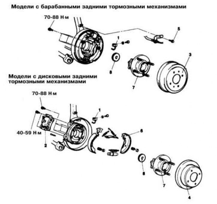
The design of the hub assembly on Galant models since 1994, no.
1 - Wheel sensor (models with ABS); 2 - Brake caliper; 3 - Brake drum; 4 - Brake disc; 5 - Support bracket bolt; 6 - Brake shoes; 7 - Rear hub; 8 - Wheel sensor rotor (models with ABS)
Mirage models through 1992 no.
Removing
1. Jack up the car and put it on stands. Remove the corresponding rear wheel.
2. On models with rear disc brakes, remove the caliper and brake disc (see chapter Brake system).
3. Remove the dust cover and give the bearing nut - do not use a pneumatic drive to give the nut.
4. Remove the outer wheel bearing.
5. Remove the brake drum/hub assembly with inner bearing and seal.
6. Remove the oil seal and inner bearing from the hub assembly.
Installation
1. Lubricate the inner bearing and install it in the hub assembly/brake drum.
2. Install a new oil seal.
3. Screw on the self-locking nut so that 2-3 mm of thread remains under it. Measure the counterclockwise torque of the nut, if the measurement is less than 6 Nm, the nut must be replaced.
4. Install the brake drum/hub assembly in its proper place.
5. Lubricate the outer wheel bearing and seat it on the spindle.
6. Tighten the self-locking nut to the required torque (150÷200 Nm).
7. Using a dial gauge, determine the hub/drum end play. If the measurement result is more than 0.002 mm, repeat the nut tightening procedure. If retightening the nut does not produce the desired result, replace the bearings.
8. Install the protective cover and wheel.
9. Lower the vehicle to the ground.
Mirage models since 1993 issue.
Attention! Disassembly of wheel bearings on these models is not possible. If necessary, replace the hub assembly!
Removing
1. Jack up the car and put it on stands. Remove the corresponding rear wheel.
2. On models equipped with ABS, remove the wheel sensor.
3. Remove the caliper and brake disc/brake drum (see chapter Brake system).
4. Remove the dust cover and give the bearing nut - do not use a pneumatic drive to give the nut.
5. Remove the hub assembly.
Installation
1. Install the hub assembly in its original place. Torque tighten (180 Nm) flange nut.
2. Install the dust cover.
3. On models with ABS, reinstall the wheel sensor, - make sure that the air gap does not exceed the allowable range (0.3÷0.9 mm).
4. Install the brake disc and caliper/brake drum.
5. Install the rear wheel and lower the vehicle to the ground.
Galant models through 1993 no. with drum brakes on the rear wheels
Removing
1. Jack up the car and put it on stands. Remove rear wheels.
2. Remove a protective cover and give a nave nut.
3. Remove the brake drum (see chapter Brake system). The outer wheel bearing should fall out of the hub when the drum is removed - try not to drop it.
4. Remove the hub assembly.
5. Remove the inner bearing.
6. Check the condition of the bearing components. If scratches, scuff marks or overheating marks are found on the surfaces of the clips, the latter are replaced by the whole set - the clips to be replaced are knocked out using a brass punch.
Installation
1. Before installing, the bearing races should be lubricated with special bearing grease. Follow the completeness of the landing of the clips - use a suitable mandrel.
2. Thoroughly pack the bearings with grease, the remainder of which lubricate the hub.
3. Install the inner bearing, lubricate and seat a new oil seal - use a special mandrel.
4. Install the brake drum (see chapter Brake system).
5. Lubricate and install the outer bearing, install the washer and nut.
6. While rotating the drum, tighten the nut to 17 Nm, then loosen it to remove the preload and tighten again, this time to 10 Nm.
7. Lock the nut and install a new cotter pin.
8. Install the wheel and lower the vehicle to the ground.
Galant models through 1993 no. with rear wheel disc brakes
Removing
1. Jack up the car and put it on stands. Remove rear wheels.
2. Turn out a fixing bolt (s) and remove the wheel sensor support bracket from the knuckle of the hub assembly.
Attention! Try not to let the sensitive element of the sensor come into contact with the teeth of the rotor!
3. Remove the brake caliper and tie it to the suspension elements (see chapter Brake system).
4. Remove the brake disc (see chapter Brake system).
5. Remove the protective cap, nut and lock washer.
6. Remove the hub assembly.
Note. The rear hub cannot be disassembled and, in the event of a bearing failure, it is replaced as an assembly.
7. If necessary (models with ABS) unscrew the two mounting bolts and remove the wheel sensor rotor from the hub to be replaced.
Installation
1. Install the wheel sensor rotor on the hub. Tighten the fixing bolts to the required torque (11 Nm).
2. Install the hub assembly in its original place.
3. Install the lock washer, screw in a new lock nut and tighten it to the required torque (200÷260 Nm). Lock the nut and install the protective cover.
4. Install the brake disc and brake caliper.
5. Install the wheel sensor and tighten the bolts of its fastening with the required force (11 Nm).
6. Install the wheel and lower the vehicle to the ground. Bleed the foot brake pedal before driving off.
Galant models since 1994 with drum brakes on the rear wheels
Removing
1. The design of the hub assembly of the considered models is shown in the illustration.
2. Jack up the car and put it on stands. Remove the corresponding rear wheel.
3. On models with ABS, remove the wheel sensor.
4. Remove the brake drum (see chapter Brake system).
5. From the back of the knuckle, remove the four hub mounting bolts.
6. Remove the hub from the knuckle.
Attention! The hub cannot be disassembled!
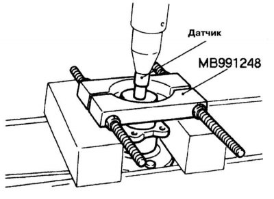
7. If necessary (models with ABS) remove the wheel sensor rotor from the hub to be replaced, - use the special head type MB991248.
Installation
1. Press the wheel sensor rotor onto the new hub (models with ABS).
2. Install the hub on the knuckle and tighten the mounting bolts with the required force (74÷88 Nm).
3. Install the brake drum (see chapter Brake system).
4. On models with ABS, install the wheel sensor.
5. Install the wheel and lower the vehicle to the ground.
Galant models since 1994 with rear wheel disc brakes
Removing
1. The design of the hub assembly of the considered models is shown in the illustration.
2. Remove the cotter pin and give the hub nut. Remove the puck.
3. Jack up the car and put it on stands. Remove the corresponding rear wheel.
4. On models with ABS, remove the wheel sensor.
5. Remove the caliper and tie it to the suspension elements (see chapter Brake system).
6. Remove the brake disc (see chapter Brake system).
7. Remove the upper anchor springs of the parking brake friction shoes.
8. Remove the lower friction shoe return spring.
9. Remove the shoe guide springs.
10. Disconnect the drive cable from the parking brake actuating lever.
11. From the rear side of the fist of the hub assembly, give the four hub mounting bolts.
12. Remove the hub assembly with wheel bearings.
Attention! The hub cannot be disassembled!
13. If necessary (models with ABS) remove the wheel sensor rotor from the hub to be replaced, - use the special head type MB991248.
Installation
1. Press the wheel sensor rotor onto the new hub (models with ABS).
2. Install the hub on the knuckle and tighten the mounting bolts with the required force (74÷88 Nm).
3. Install the friction shoes of the parking brake (see chapter Brake system).
4. Install the brake disc on the hub and temporarily secure it by screwing on a pair of wheel nuts.
5. Establish an anchor bracket of the brake mechanism and enclose in it brake pads.
6. Install the brake caliper, then remove the temporary wheel nuts.
7. On models with ABS, install the wheel sensor.
8. Install the wheel and lower the vehicle to the ground.
Diamante Models
Attention! The hub on these models is not subject to refurbishment and in case of failure of the components must be replaced as an assembly!
Removing
1. Jack up the car and put it on stands. Remove the corresponding rear wheel.
2. Remove the brake caliper and brake disc (see chapter Brake system). Tie the caliper with wire to the suspension elements.
3. On models with ABS, remove the mounting bolt and remove the wheel sensor from the trailing arm.
Attention! Try not to let the sensitive element of the sensor come into contact with the teeth of the rotor!
4. Remove the protective cover, give the self-locking hub nut and remove the lock washer.
5. Remove the hub assembly from the wheel axle spindle.
6. If necessary, give the fixing bolts and remove the wheel sensor rotor from the hub (models with ABS).
Installation
1. Attach the wheel sensor rotor to the hub (models with ABS).
2. Install the hub in its regular place. Screw on a new self-locking nut (do not forget to put a lock washer) and tighten it to the required torque (230 Nm), - check the correct alignment of the landing marks.
3. Using a dynamometer and a cord wrapped around the bolt heads, measure the turning force of the hub assembly. If the measurement result exceeds 10 N, repeat the procedure for tightening the nut. Replace hub if necessary.
4. Using a dial gauge, determine the end play of the hub assembly, the maximum allowable value is 0.05 mm.
5. Install the brake disc and brake caliper.
6. On models with ABS, reinstall the wheel sensor - make sure its wiring is correct.
7. Using a non-magnetic blade-type feeler gauge, measure the air gap between the sensor element and the signal rotor teeth. The required value is 0.2÷0.7 mm. tighten the sensor support bracket nut and recheck the air gap at various points on the rotor. Replace rotor if necessary.
8. Bleed the brake circuit and reinstall the rear wheel.