
English Русский
Български
Беларускі
Український
Српски
Hrvatski
Română
Polski
Slovenský
Magyar
Articles Bookmark Contacts Sitemap   
Company Audi Company Ford Company Hyundai Company Kia Company Mazda Company Mercedes-Benz Company Nissan
MitsubishiMan.ru


Home Colt Lancer Galant L200 Outlander Pajero Others
Galant 6 and 7 (1987-1998) Galant 5 (1983-1989, petrol)

Brake disc — inspection, removal and installation (Mitsubishi Galant 5)

  • Home
  • Galant
  • 5 (1983-1989, petrol)
  • Chassis and running gear
  • Brake system
  • Brake disc — inspection, removal and installation
0
Contents: Inspection ⤓ Removal and installation ⤓
1. Loosen the wheel nuts, jack up the car and place it on supports. Remove the wheel.

2. Remove the brake mechanism, pads and caliper as described in section 4. It is not necessary to disconnect the brake pipe. After unscrewing the brake mechanism mounting bolts, hang the brake mechanism using a piece of wire (see illustration).

Note: On some models, the brake disc may slip off the hub after the brake assembly and caliper are removed. If your vehicle has this design, install the wheel nuts and tighten them securely before checking the disc.


Inspection


3. Inspect the disc surface for scratches and damage. Shallow scratches and grooves are normal and do not affect brake performance, but deep nicks (more than 0.36 mm) require the disc to be removed and treated in a mechanical workshop. Check both sides of the disc. If pulsation is felt during brake operation, check the disc runout.

The material was copied from the website MitsubishiMan.ru

4. To check the disc runout, place a dial indicator at a point 1.25 mm from the outer edge of the disc (see illustration). Reset the indicator to zero, then rotate the disc. The difference between the highest and lowest indicator readings should not exceed the permissible limits. Otherwise, the disc surface should be treated in a machine shop.
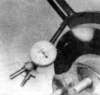


5.4a. To check the ovality of the disk, a dial indicator is used; if the readings are outside the permissible tolerance, the disk must be mechanically processed or replaced


Note: It is recommended to treat the disc surface regardless of the dial indicator readings, because after treatment the disc surface will be smooth and completely flat, which will eliminate the pulsation of the brake pedal or other symptoms associated with an untreated disc. If you decide not to treat the disc surface in a machine shop, at least treat the disc surface with sandpaper in a circular motion.


5. The disc can only be machined to the minimum thickness. The minimum wear thickness is imprinted on the inside of the disc. The disc thickness can be checked with a micrometer.
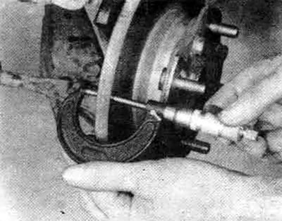


5.5b. Using a micrometer, measure the thickness of the disc at several points


Removal and installation


6. As stated above, on some models the brake disc may slip off the hub after removing the brake mechanism and support disc. If you have a car of this design, unscrew the three nuts screwed to secure the disc, then remove the disc from the hub.

7. Following the description given in Chapter 10, remove the hub with the steering knuckle.

8. Take the hub with the steering knuckle to a car repair shop, because special tools are required to remove and install the hub and disc on the steering knuckle and to properly adjust the hub bearing tension.


9. Install the hub and steering knuckle as described in Chapter 10.

10. Install the brake mechanism, support disc and pad assembly over the disc and position it on the steering knuckle (if necessary, refer to the brake mechanism installation procedure see section 4). Tighten the support plate mounting bolts or studs to the appropriate torque specified in the specifications in this Chapter.

11. Install the wheel, then lower the vehicle to the ground. Press the brake pedal firmly several times to ensure that the brake pads come into contact with the disc. If the brake line has not been disconnected from the brake mechanism, there is no need to bleed the system. Before starting normal operation of the vehicle, carefully check the brakes for proper operation.
This article is available at: russian, bulgarian, belarusian, ukrainian, serbian, croatian, romanian, polish, slovak, hungarian
This article was reviewed by: Vladimir Glazunov
Share with friends:
◀ Previous
Galant 5: Brake system
Next ▶

Disc brake mechanism — removal, overhaul and installation
Disc brake pads (front and rear) — replacement
Anti-lock braking system (ABS) — general description
Brake system — general description
Brake system — specification
Drum brake shoes — replacement
Wheel brake cylinder — removal, overhaul and installation
Master Brake Cylinder — Removal, Overhaul and Installation
Brake force regulator — removal and installation
Brake Hoses and Tubes — Inspection and Replacement
Similar materials for other Mitsubishi models

➤ Measuring the thickness of the front disc brake pads Mitsubishi Colt 4 and 5 (1991-2003)
➤ Removal and installation rear disc brake pads Mitsubishi Lancer 3 and 5 (1984-1992)
➤ Removal the front wheel brake disc Mitsubishi L200 4 (2005-2014, diesel)
➤ Checking the brake disc Mitsubishi Outlander 1 (2003-2008)
➤ Front Disc Brake Pads — Removal and Installation Mitsubishi Pajero 1 and 2 (1982-1999)
➤ Checking the thickness of the brake disc Mitsubishi Carisma (1995-2004)
Link in different formats to this article
Comments and feedback from visitors
No comments yet


Add up two numbers 44 + 50


Galant 6 and 7 (1987-1998) 
  • General information
  • Introduction to guide
  • User manual
  • Driving and operation
  • Maintenance
  • Power unit
  • Dismantling the engine
  • Engine overhaul
  • Cooling and heating
  • Power and exhaust systems
  • Engine electrical equipment
  • Engine management systems
  • Transmission
  • Mechanical gearbox
  • Automatic gearbox
  • Clutch
  • Drive shafts and transfer case
  • Chassis and running gear
  • Brake system
  • Car suspension
  • Steering
  • Body and interior
  • Exterior (external elements)
  • Interior (internal elements)
  • Doors, locks and windows
  • Electrical equipment
  • Equipment and devices
  • Wiring diagrams Galant
  • Wiring diagrams Mirage
  • Wiring diagrams Diamante
Galant 5 (1983-1989, petrol) 
  • General information
  • Troubleshooting
  • Maintenance
  • Power unit
  • Engine repair
  • Engine overhaul
  • Cooling and heating
  • Fuel and exhaust system
  • Engine electrical equipment
  • Reducing exhaust toxicity
  • Transmission
  • Manual gearbox
  • Automatic gearbox
  • Clutch and drive shafts
  • Chassis and running gear
  • Brake system
  • Car suspension
  • Steering
  • Body and interior
  • Exterior (external elements)
  • Interior (internal elements)
  • Doors, locks and windows
  • Electrical equipment
  • Equipment and devices
  • Electrical diagrams
MitsubishiMan.ru © 2018–2026 • Mobile version • Articles about Mitsubishi • Contacts • Sitemap: EN BG BY UA RS HR RO PL SK HU • Site search • Bookmark
Colt 2 and 3 (1983-1993) · Colt 4 and 5 (1991-2003) · Colt 5 (1995-2003) · Lancer 3 and 5 (1984-1992) · Lancer 9 (2000-2007) · Galant 5 (1983-1989) · Galant 6 and 7 (1987-1998) · L200 4 (2005-2014) · Outlander 1 (2003-2008) · Pajero 1 and 2 (1982-1999) · Pajero 4 (2006-2021) · Carisma (1995-2004) · Space Star (1998-2005) ·
This resource sets cookies 🍪 to avoid bothering you with repeated data entry.