



Contents: Removal ⤓ Installation ⤓
Note: Individual components of the left and right wheel brake mechanisms differ; therefore they are not interchangeable. When removing parts, lay them out so that they can be installed in their original places.
Removal
Carefully knock off grease cap "1" with a plastic or rubber hammer.
Tighten the handbrake, loosen the self-locking nut "2" without unscrewing it.
Mark the position of the wheel disk on the wheel hub with paint. This ensures that the balanced wheel can be reinstalled in its original position.
Raise the rear of the car, see item 29.
Remove the wheel.
Release the handbrake.
Unscrew nut "2" and remove brake drum "4" with outer wheel bearing "3". Make sure that the bearing does not fall out.
Caution: After removing the brake pads, do not press the brake pedal, as the piston will come out of the brake cylinder.
Before removing the return springs, it is recommended to mark their mounting position. This will facilitate subsequent installation.
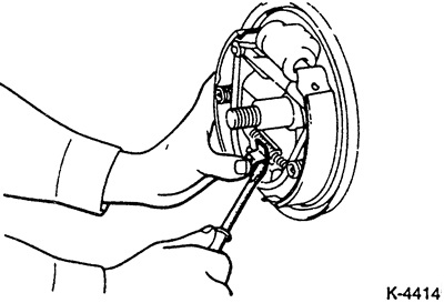
Cars produced from 1.84 to 5.90: press the clamping spring with a large screwdriver, as shown in the figure.
Disconnect the return springs with a suitable screwdriver or pliers.
Caution: Spring "11" (brake type 2) is under high tension. Risk of accident!
Remove the installation lever and installation element.
Press the spring cup firmly with pliers and turn it 90°. While pressing, hold the locking pin on the back of the brake shield.
Disconnect the lower spring from the front brake shoe and remove the front brake shoe.
Tilt the rear brake shoe down and disconnect the handbrake cable from the handbrake lever.
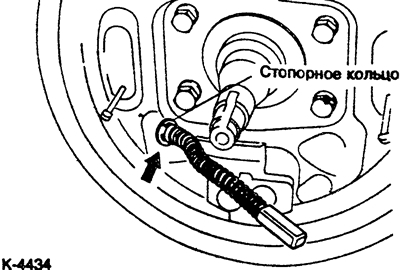
If it is necessary to remove the handbrake cable, disconnect it from the brake shield. To do this, compress the spring with pliers and pull out the retaining ring with a screwdriver.
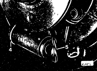
Remove the dust boot from the working brake cylinder "5".
Note: The cylinder piston should not come out. Check if it is dry behind the dust boot. If there is moisture, replace the wheel brake cylinder.
Place the dust boot on the working brake cylinder.
Installation
Always replace all 4 brake pads at the same time, even if only one of the brake pads has reached the wear limit. Install brake pads of only one type. Clean the brake drum and brake caliper with a vacuum cleaner or alcohol. If the brake cylinder is wet with brake fluid, replace the cylinder. Ensure that the threads of the installation tool move easily and lightly lubricate with MоS ₂ grease. Ream brake drums that have scratches and grooves, while treating both drums at the same time. Take into account the upper permissible drum diameter (wear limit), see paragraph 18.17.
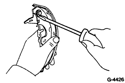
Move the handbrake lever from the old to the new brake shoe.
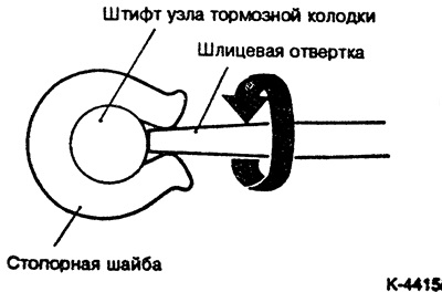
To do this, loosen the lock washer and remove the thrust washer.
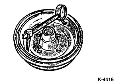
Measure the brake drum diameter in at least 2 places. When the wear limit is reached or wear is very uneven, replace the left and right brake drums and brake shoes.
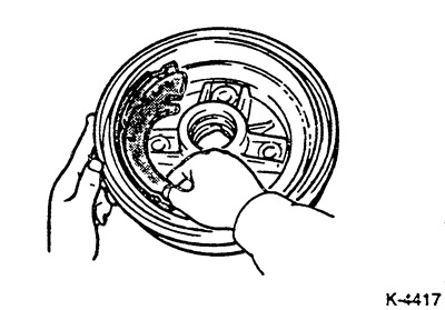
Check the compatibility of the brake drum shape and brake shoes. To do this, cover the inner surface of the brake drum with a layer of chalk and rub it with a brake shoe. If the contact surface is very uneven, replace the brake shoe.
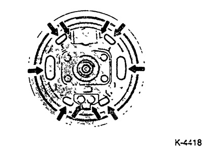
Clean the contact areas between the brake pads and the brake shield, the brake pads and the retaining pins, and the rear surface of the piston, and coat with a thin layer of heat-resistant grease, preferably high-temperature copper paste, before installing the brake pads.
Also lightly lubricate the threads and contact points of the mounting element. Caution: Do not allow grease to come into contact with the brake pads and brake linings.
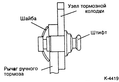
Place the handbrake lever and install the thrust washer as shown in the figure.
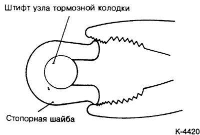
Use pliers to install the lock washer.
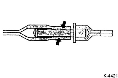
Lubricate the threaded part and the inner surface of the coupling with high-temperature paste. Brake paste SAE J310 NLGI Nr.1 can be used.
If removed, connect the handbrake cable to the brake shield guide. To do this, use pliers to tighten the spring and insert the retaining ring.
Connect the handbrake cable to the handbrake lever.
Install the brake shoe and secure it with the locking pins, cups and springs. Hold the locking pins from behind and simultaneously press the spring cup with pliers and secure it by turning it 90°.
Insert the return springs into the brake shoes using brake spring pliers.
Note: Pay attention to the correct position of the return springs, see pictures.
Check the operation of the automatic installation device. To do this, move the handbrake lever on the rear brake shoe back and forth. The installation screw should turn. If the installation screw does not turn, the cause is usually incorrect installation of the brake shoes, repeat the installation.
Using a screwdriver, turn the setting roller to the position of the shortest adjustable length.
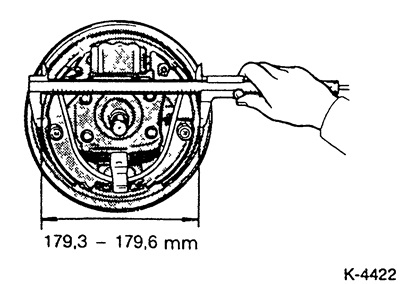
Turn the adjusting screw to adjust the outer diameter of the brake pads to the required value.
Caution: The handbrake lever must be released. When the lever is pulled by the handbrake cable, the automatic setting of the brake shoes does not function.
Put on the brake drum.
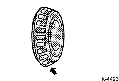
Apply bearing grease to the inner race of the outer bearing.
Insert the hub bearing and screw on the new hub nut without tightening it.
Position the wheels according to the markings, screw in the wheel nuts. Lower the car and tighten the nuts crosswise. Tightening force see item 19.4.
Tighten the hub nut with the vehicle on the ground.
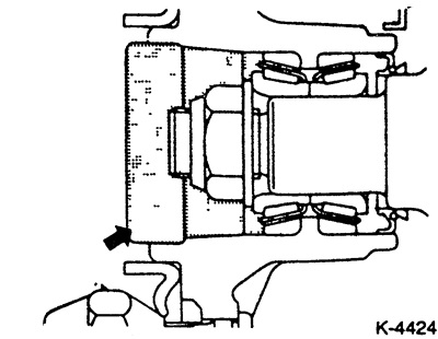
Fill the grease cap with bearing grease and install it.
By pressing the brake pedal repeatedly, perform the basic setting of the clearance in the rear wheel brakes. In this case, until the clearance is set, clicks are heard in the brakes.
Adjust the handbrake.
On the road, in the absence of vehicles, perform test braking at an average speed.
The original material is here MITSUBISHIMAN