
Removing
To remove the wheel speed sensor, perform the following steps.
Front wheel
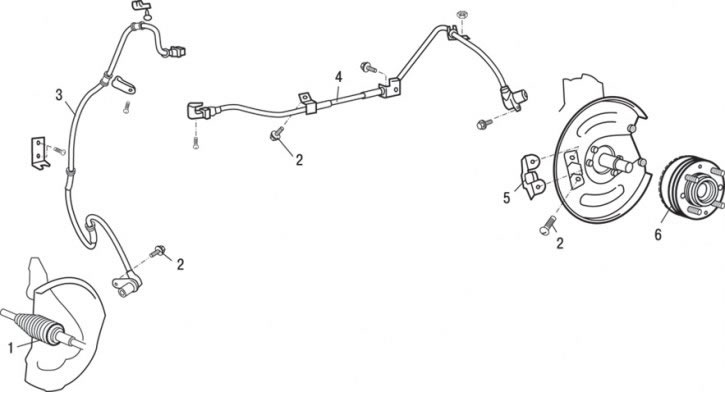
Pic. 14.50. Front and rear wheel speed sensors: 1 – a rotor of the gauge of frequency of rotation of a forward wheel; 2 - bolt (25 Nm); 3 - front wheel speed sensor; 4 – the gauge of frequency of rotation of a back wheel; 5 – sensor bracket; 6 – a rotor of the gauge of frequency of rotation of a back wheel
1. Turn out a bolt and remove the gauge 3 (pic. 14.50) front wheel speed.
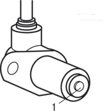
Pic. 14.51. Location of the pole piece (1) wheel speed sensor
Attention! Take care when handling the wheel speed sensor pole piece and the toothed surface of the rotor to avoid damaging them with other parts (pic. 14.51).
2. Remove rotor 1 (see fig. 14.50) front wheel speed sensor together with the front wheel drive shaft. The front wheel speed sensor rotor is integrated with the front wheel drive shaft and is non-separable.
Rear wheel
1. Turn out a bolt and remove the gauge 4 of frequency of rotation of a back wheel.
2. Turn out two bolts and remove an arm 5 of the gauge.
3. Remove the rotor 6 of the rear wheel speed sensor.
Examination
1. Check the surfaces of the sensor pole piece for any metal particles and remove if any.
2. Also check the pole piece for damage, and if found, replace the sensor.
3. Since a magnet is installed inside the speed sensor, the pole of the sensor is magnetized, as a result of which foreign metal objects are easily attracted to it. In addition, if the pole piece is damaged, the sensor will not be able to correctly detect the wheel speed.
4. Measure the resistance between the sensor leads, which should be in the range of 1.28–1.92 kOhm.
5. If the internal resistance of the wheel speed sensor is out of specification, replace the sensor.
6. Check the sensor wires for damage, breakage or poor contact; if any are found, replace the wire with a new one.
To check for damage to the sensor wire, remove the wire clamp from the body, then bend and pull on the wire to check for a temporary loose connection.
Installation
Installation is carried out in the reverse order of removal, taking into account the following.
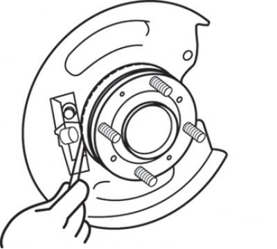
Pic. 14.52. Measuring the gap between the pole piece of the wheel speed sensor and the toothed surface of the rotor
1. When installing the rear wheel speed sensor, insert a feeler gauge into the gap between the wheel speed sensor pole piece and the toothed surface of the rotor, set the nominal gap around the entire perimeter of the rotor within 0.3-0.9 mm, and tighten the sensor bracket (pic. 14.52).
Attention! Be careful when handling the wheel speed sensor pole piece and the toothed surface of the rotor to avoid damaging them with other parts.
2. Check the output voltage of the sensor.