



Front (top) and rear wheel speed sensor
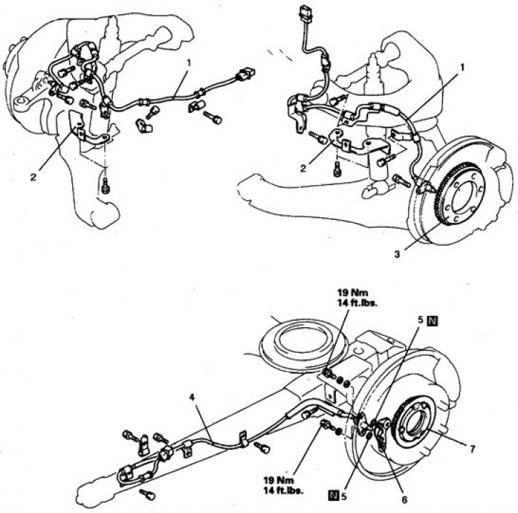
On the front wheels: 1. Sensitive element of the sensor; 2. Bracket; 3. Rotor
On the rear wheels: 4. Sensor sensing element; 5. Seal; 6. Bracket; 7. Rotor; N – the part is subject to replacement during assembly
Examination
1. Remove the sensor and toothed rotor.
2. If damage or metal deposits are detected on the sensor pole piece due to magnetic attraction, replace the sensor.
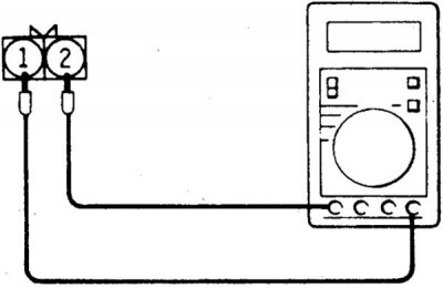
3. Check the resistance between the sensor terminals. For front wheel sensors, the resistance should be 900–1100 Ohm, for rear wheel sensors – 1300–2100 Ohm.
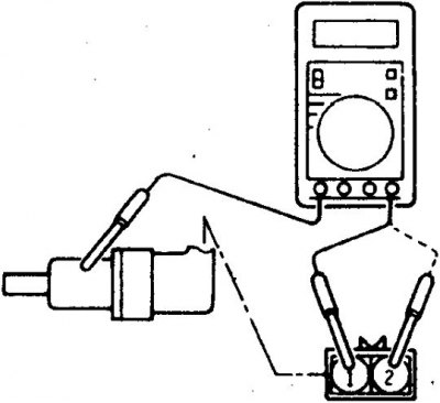
4. The resistance of the sensor to the body must be at least 100 kOhm.
5. Otherwise, replace the sensor.
6. Replace the sensor if it is visibly damaged.
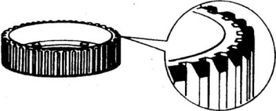
7. Check the condition of the rotor teeth. Replace the rotor with worn or broken teeth.
Removal and installation
Front wheel sensors
1. Disconnect the battery from ground, lift the car and remove the wheel.
2. Disconnect the connector from the sensor, remove the clamps and take out the wiring.
3. Unscrew the 2 bolts on the steering knuckle and carefully, without causing impact, remove the magnetic part of the sensor from the knuckle.
4. Remove the wiring bracket.
5. Remove the hub with the disc (see subsection 9.3.12, subsection 9.3.13) and remove the sensor rotor by unscrewing the bolts.
6. Installation is carried out in reverse order.
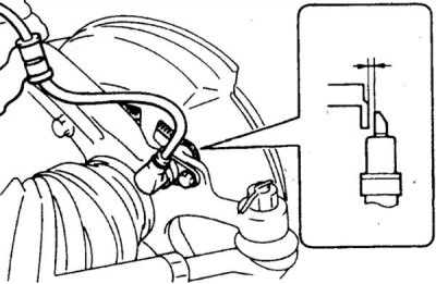
7. Maintain a gap of 0.2–1.0 mm between the sensor head and the rotor ring. If this gap is violated, check that the rotor is installed correctly.
8. If the sensor has been changed, have the system checked at a car service center.
Rear wheel sensors
1. Disconnect the battery from ground, lift the vehicle and remove the rear wheel.
2. Disconnect the connector from the sensor on the rear suspension arm, remove the brackets on the bridge beam and remove the wiring.
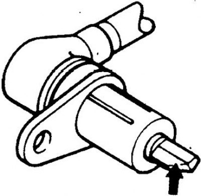
3. Unscrew the 2 bolts on the brake shield and carefully remove the sensitive element of the sensor and the sealing rings.
4. Remove the axle shaft (see subsection 9.4.1) and the brake disc, remove the rotor and sensor bracket.
5. Installation is carried out in reverse order.
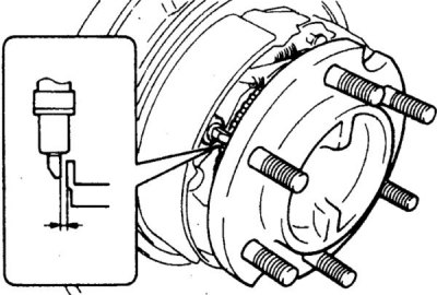
6. Maintain a gap of 0.3–0.9 mm between the sensor head and the rotor ring. If this gap is violated, check that the brake disc is installed correctly.
7. If the sensor has been changed, have the system checked at a car service center.