



Removal
1. Remove the valve cover (see section 3).
2.. Set the piston of the first cylinder to the top dead center (see Chapter 2B)
3 Loosen the rocker shaft mounting bolts 1/4 turn at a time until the spring tension is completely released. Remove the bolts. If you are working on a DOHC engine, remove the camshafts according to the procedure in section 9.
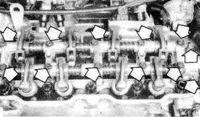
4.3. Unscrew the valve rocker shaft bolts (arrows) 2.0L Galant engine shown
4. Remove the rocker arms and shaft assembly, or the rocker arms separately from the cylinder head. If you are working on an engine with hydraulic valve adjustment, be careful that the adjusters do not fall out of the rocker arms. To secure the adjusters, wrap the ends of the arms with tape.
Examination
5. If you want to disassemble and check the rocker arms (since you removed them), unscrew the mounting bolts and remove the arms and springs from the shafts. Lay the parts one by one so that when you reassemble them, you can put them back in their original position.
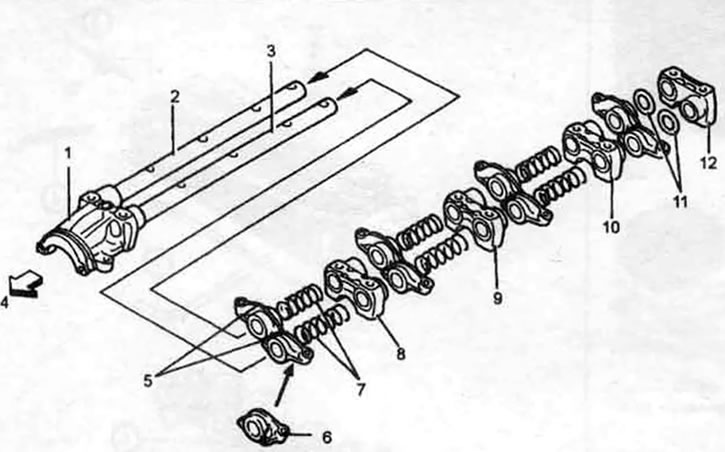
4.5. Exploded view of valve rocker arms and axles (typical). 1. Front cover; 2. Right axis; 3. Left axle (longer than the right); 4. To the crankshaft pulley; 5. Valve Rockers (Canadian vehicles use the same valve rockers for both intake and exhaust valves); 6. Intake Rocker Arm (US vehicles only); 7. Right spring - free length 63.3 mm; 8. Cover No.2; 9. Cover No.3; 10. Cover No.4; 11. Wave washer; 12. Back cover
6. Clean the components thoroughly and check for wear and damage. On SOHC engines, check the condition of the surface that contacts the camshaft and the tips of the adjusting screws. On DOHC engines, visually inspect the rollers for dents, damage, and seizure. Replace any damaged or worn components. Also check the oil passages in the shafts for patency.
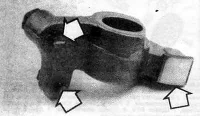
4.6. Check the condition of the contact surfaces and ends of the adjusting screws (arrows)
Installation
7. On the valve rocker arms with adjusting screws, loosen the lock nuts and recess the adjusters so that they protrude only 1 mm.
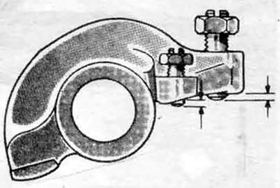
4.7. On adjustable type rocker arms, back out the adjusters so that they protrude only 1 mm
The article was obtained from this portal [mitsubishiman.ru]
8. Lubricate all parts with engine assembly grease and assemble the rocker arm shaft (SOHC engine). When installing the rocker arms, shafts and springs, pay attention to the markings and the difference between the left and right parts. On 8-valve SOHC engines, install the shafts with the notches on the ends facing up. On 16-valve SOHC engines, install the shafts with the notches facing outward, so that the line connecting the notches is parallel to the surface of the cylinder head gasket. Insert bolts through the shafts (16 valves) or through the bearing caps and shafts (8 valves) to secure the parts before assembly.
9. Insert the hydraulic valve adjusters (if removed) into the rocker arms and secure them by wrapping the ends of the rocker arms with tape.
Note: New regulators are filled with diesel oil. To prevent oil from spilling, avoid tilting the regulator if possible. If oil spills from the regulator, bleed it as described in section 6.
10. Install the rocker arm shafts with the rocker arms onto the cylinder head, then tighten the bolts with finger force.
Note: On DOHC engines, bearing caps two through five are the same shape. Check the markings on the caps to ensure they correspond to the journal number and intake or exhaust position. On models with hydraulic valve adjusters, remove the tape from the rocker arms.
11. Tighten the bolts in several stages to the torque specified in specifications.
Note: On DOHC engines, tighten the cap bolts in increments, starting from the center journals and working toward the ends of the camshaft.
12. On adjustable type rocker arms, adjust the valve clearances (on a cold engine) as described in Chapter 1.
13. Temporarily install the valve cover, start the engine and warm it up to normal operating temperature.
14. Re-adjust the valve clearances on a hot engine (see Chapter 1).
15. Install the remaining parts in the reverse order of disassembly.
16. Start the engine and check for operation and leaks.