



Warning: The electric cooling fan may turn on at any time, even if the ignition is off. When working near the fan, turn off the power to it or disconnect the cable from the negative battery terminal.
Note: This procedure applies to single overhead camshaft (SOHC) engines only
1. Valve clearances should be checked and adjusted at the intervals specified in the specification, with the engine at normal operating temperature. Not all models require valve clearance adjustment - other models require adjustment of the injector valves. Consult a specialist or your owner's manual to determine if your vehicle requires valve adjustment. Otherwise, the only way to know if adjustment is necessary is to remove the valve cover. Valves that do not require adjustment do not have adjusting screws.
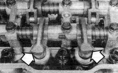
19.1 On engines that do not require valve clearance adjustment, the rocker arms look like the ones shown in this photo (arrows) - they do not have adjusting screws (if the rocker arms do not have adjusting screws for the intake, exhaust or smaller injector valves, follow the recommendations in the text)
2. Remove the air filter (see Chapter 4).
3. Remove the valve cover (see Chapter 2). On some models, to gain access to the front valve cover bolts, it is necessary to support the engine and remove the front engine mount.
Note: The engine can be supported from above with a winch or from below with a jack placed under the oil pan. When using a jack, place a wooden block under the pan to better distribute the load.
4. Set the piston of the first cylinder to the top dead center (TDC) position on the compression stroke (see Chapter 2). The valve rocker arms of the first cylinder (closest to the timing belt) should be free (able to move up and down a little), and the camshaft lobes should point away from the valve rocker arms.
5. With the crankshaft in this position, you can check and adjust the clearances of the valves marked with the letter A (as well as the injector valves located next to the intake valves). Always check and adjust the clearances of the injector valves first.
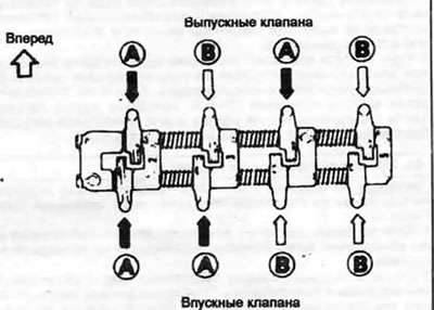
19.5. Having set the piston of the first cylinder to TDC, adjust the valve clearance with mark A - having set the piston of the fourth cylinder to TDC, adjust the valve clearance with mark B
6. The adjusting screws of the intake valve and the injection valve are located on the common valve rocker. Turn the adjusting screw of the intake valve two full turns, then loosen the lock nut of the adjusting screw of the injection valve.
7. Turn the adjusting screw of the injection valve counterclockwise and insert a flat feeler gauge of the appropriate thickness (see specification in this chapter) between the valve stem and the adjusting screw. Carefully tighten the adjusting screw until a slight resistance is felt when the feeler gauge is removed from the gap between the stem and the adjusting screw.
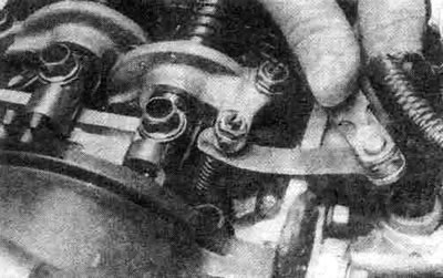
19.7. When pulling a flat feeler gauge between the adjusting screw of the injector valve and the valve stem, a slight resistance should be felt
8. Since the injector valve spring is relatively weak, pay special attention not to open the injector valve. Be especially careful if the adjusting screw is difficult to turn. Hold the adjusting screw with a screwdriver to prevent it from turning, and tighten the lock nut. Check the clearance again.
9. Then check and adjust the intake valve clearance. Insert a flat feeler gauge of appropriate thickness between the valve stem and the adjusting screw. Carefully tighten the adjusting screw until a slight resistance is felt when the feeler gauge is removed from the gap between the stem and the adjusting screw.
10. Hold the adjusting screw from turning with a screwdriver and tighten the lock nut. Check the clearance again.
11. Loosen the lock nut of the exhaust valve adjusting screw. Turn the adjusting screw counterclockwise and insert a flat feeler gauge of the appropriate thickness between the valve stem and the adjusting screw. Carefully tighten the adjusting screw until a slight resistance is felt when the feeler gauge is removed from the gap between the stem and the adjusting screw.
12. Hold the adjusting screw with a screwdriver to prevent it from turning and tighten the lock nut. Check the clearance again.
13. Turn the crankshaft so that the piston of the fourth cylinder is at TDC on the compression stroke. The valve rocker arms of the fourth cylinder (closest to the gearbox) are released, and the camshaft lobes are directed away from the valve rocker arms.
14. Adjust the valves marked B as described in points 4-8.
15. Reinstall the valve cover and air filter.