



Note: Broken valve springs and damaged valve stem seals can be replaced without removing the cylinder head. This operation usually requires two special tools and a source of compressed air, so read this section carefully and purchase the necessary tools before beginning the work. If compressed air is not available, use a piece of nylon cord to prevent the valves from falling into the cylinders.
Note: Some engines are equipped with a pilot valve or injection valve. The injection valve is located immediately after each exhaust valve. The injection valve service procedure is described in Chapter 2B.
1. Remove the valve cover as described in section 3.
2. Unscrew the spark plug from the cylinder that has faulty elements. If it is necessary to replace all the oil scraper caps, then unscrew all the spark plugs.
3. Turn the crankshaft so that the piston of the cylinder you are working with is at TDC on the compression stroke (see Chapter 2B). If you are replacing all the valve stem seals, start with the first cylinder and proceed cylinder by cylinder, working on only one cylinder at a time. Proceed from cylinder to cylinder in the spark sequence (see specification).
4. Screw the adapter into the spark plug hole and connect a hose from a compressed air source to it.
Note: Many compression testers have male fittings that may be suitable for connecting an air hose.
5. Remove the rocker arm shaft (see section 4), unless you are using a lever type fixture.
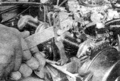
5.5 If you use the special tool shown here, leave the intake rocker shaft in place when replacing the exhaust seals and vice versa
6. Supply compressed air to the cylinder.
Warning: The compressed air can force the piston downwards, causing the crankshaft to turn suddenly. If the wrench used to set the No.1 cylinder piston to TDC is left on the crankshaft bolt, it can cause injury when the crankshaft turns.
7. The valves should be held in place with compressed air. If the valve surfaces or seats are in poor condition, air leaks will prevent the valves from being held in place - use the alternative procedure below.
8. If you do not have access to compressed air, try an alternative method. Set the piston to a position a few degrees before TDC on the compression stroke, then insert a long piece of nylon cord into the combustion chamber through the spark plug hole. Leave the end of the cord outside so that you can remove the cord. Using a ratchet socket wrench, turn the crankshaft in the normal direction of rotation until you feel a slight resistance.
9. Plug the cylinder head openings above and below the valves with a rag to prevent parts and tools from falling into the engine, then compress the valve spring with a special device. Use a magnet or needle-nose pliers to remove the crackers.
Note: To compress the valve springs without removing the cylinder head, you can use different types of devices. One type of device is fixed to the lower coil of the spring and presses on the holder as the handle is turned, while another type of device uses a lever resting on the rocker shaft.
10. Remove the spring plate and valve spring, then remove the valve stem seal.
Note: If the compressed air does not hold the valve closed during this operation, the valve surface and/or seat may be damaged. In this case, the cylinder head must be removed for further repair.
11. Place a rubber band or electrical tape around the top of the valve stem to prevent it from falling into the combustion chamber, then release the air pressure.
Note: If a cord was used instead of compressed air, turn the crankshaft slightly in the direction opposite to normal rotation.
12. Check the condition of the valve stems. Rotate the valve in the guide. Check for eccentricity, which means that the valve is bent.
13. Move the valve up and down in the guide to check for jamming. A jammed valve means the valve is warped or the guide is damaged. In both cases, the cylinder head must be removed for further repair.
14. To hold the valves closed, apply compressed air to the cylinder again, then remove the tape or rubber band from the valve stem. If a cord was used instead of compressed air, turn the crankshaft in the normal direction of rotation until a slight resistance appears.
15. Lubricate the valve stem with engine oil and install a new valve stem seal.
16. Install the spring on the valve.
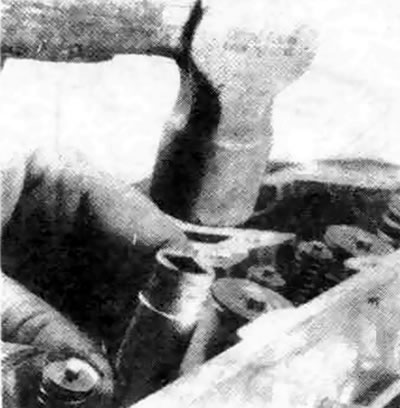
5.16. Carefully press the cap into place using a hammer and spring socket
17. Replace the spring retainer. Compress the valve spring and carefully install the crackers into the groove. If necessary, apply a small amount of grease to the crackers to secure them in place.
18. Loosen the spring compressor and make sure the crackers are in place.
19. Disconnect the air hose and remove the adapter from the air inlet. If a cord was used instead of compressed air, remove it from the cylinder.
20. Reinstall the valve rocker arms and axles as described in section 4.
21. Install the spark plugs and connect the wires.
22. Reinstall the valve cover as described in section 3.
23. Start the engine, check for leaks and unusual sounds in the valve cover area.