



Contents: Disassembly ⤓ Examination ⤓ Valve Plate Thickness (mm): ⤓ Table. Total valve length (mm). ⤓ Table. Valve stem protrusion (mm)). ⤓ Table. Valve spring height. ⤓ Spring installation length (mm)…⤓ Repair ⤓ Table. Repair dimensions (internal…⤓ Table. Repair dimensions (diameters)…⤓ Assembly ⤓
Disassembly
Caution: Arrange the removed parts according to cylinder number and intake/exhaust valves to avoid confusion during assembly.
The parts are removed in the order of numbers indicated in the corresponding figure.
When removing parts, pay attention to the following operations:
1. Removing the valves.
a) Using a special puller, compress the valve spring and remove the crackers.
b) Carefully remove the puller. Remove the spring plate, spring and its seat. Take out the valve.
Note: Keep each valve part separate.
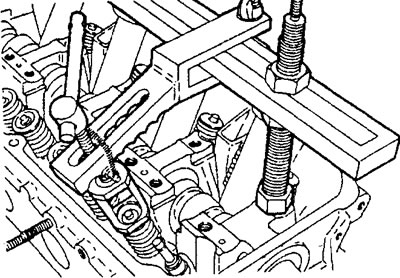
MPI engine
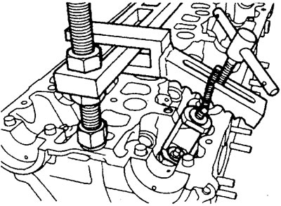
GDI engine.
2. Removing the valve stem seals.
Remove the oil seals from the cylinder head using special pliers, as shown in the figure.
Caution: Do not reuse valve stem seals.
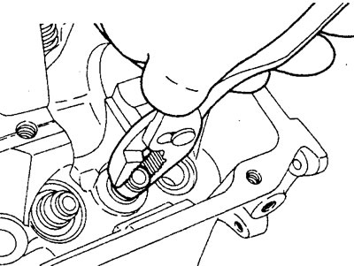
MPI engine.
Examination
Checking the cylinder head
1. Before cleaning, check the cylinder head for damage and cracks, coolant and oil leaks, exhaust gases and air.
2. Completely remove oil deposits, scale, gasket residue, and carbon deposits from the cylinder head surface. After cleaning, blow out the cylinder head oil passages with compressed air.
3. Checking the non-flatness of the mating surface of the cylinder head.
a) Using a precision ruler and a flat feeler gauge, check the non-flatness of the cylinder head gasket mating surface in directions from "A" to "G" shown in the figure.
Not flat (for head):
- Nominal - 0.03 mm
- Maximum permissible - 0.20 mm
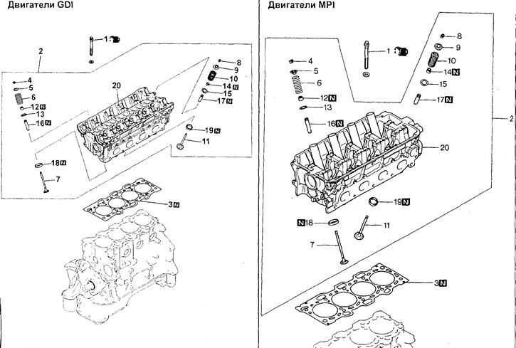
Cylinder head and valves. 1 - cylinder head fastening bolt, 2 - cylinder head assembly, 3 - cylinder head gasket, 4 - crackers, 5 - valve spring plate, 6 - valve spring, 7 - intake valve, 8 - crackers, 9 - valve spring plate, 10 - valve spring, 11 - exhaust valve, 12 - oil scraper cap, 13 - valve spring seat, 14 - oil scraper cap, 15 - valve spring seat, 16 - intake valve guide sleeve, 17 - exhaust valve guide sleeve, 18 - intake valve seat, 19 - exhaust valve seat, 20 - cylinder head.
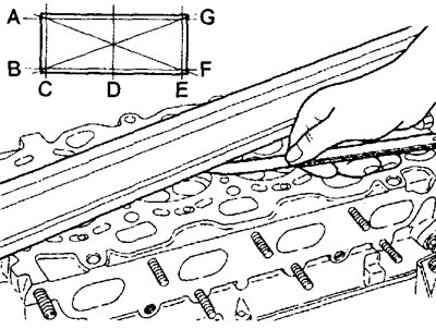
b) If the flatness exceeds the maximum permissible value, then grind the surfaces of the cylinder head and cylinder block.
Nominal height (new) of cylinder head (+0.1 mm):
- GDI Engine - 132.0mm
- MPI Engine—120.0mm
- Maximum permissible grinding depth is 0.20 mm
Attention: the total thickness of the metal removed from the mating surfaces of the cylinder head and cylinder block must not exceed 0.20 mm in total.
c) Using a precision ruler and a flat feeler gauge, check the non-flatness of the mating surface of the cylinder head under the gasket on the intake and exhaust manifold side.
Non-flatness (for collectors):
- Nominal value no more than 0.15 mm
- The maximum permissible value is 0.20 mm
d) If the flatness exceeds the maximum permissible value, then grind the mating surface of the cylinder head on the manifold side.
4. Inspect the inner surfaces under the camshaft bearings, check for scoring and other damage. If there is damage, replace the cylinder head.
Checking the valve and valve seat
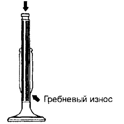
1. The valve must be replaced if the valve stem is worn (ridge wear) or damaged, or if dents have formed on the end of the valve stem (the point of contact between the end and the valve rocker adjusting screw).
2. Check the correctness of the contact patch of the valve plate chamfer with the valve seat. The contact patch should be located evenly along the center of the working chamfer of the valve plate. If the valve does not contact the seat correctly, grind the chamfer of the valve plate.
Note: Before checking the contact patch, make sure the valve and guide sleeve are in normal condition.
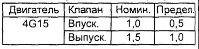
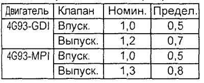
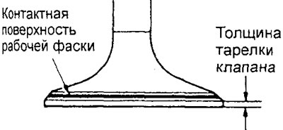
3. Check the thickness of the valve plate in its cylindrical part. If the thickness of the valve plate is less than the maximum permissible value, replace the valve.
Valve Plate Thickness (mm):
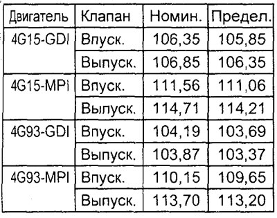
4. Measure the overall length of the valve. If the measured value is outside the permissible range (more than 0.5 mm or less than 0.5 mm from the nominal value), replace the valve.
Table. Total valve length (mm).
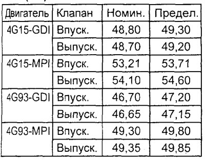
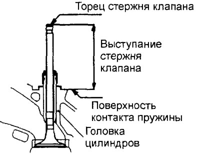
5. Insert the valve into the guide bushing in the cylinder head and, pressing it against the seat, measure the valve stem protrusion from its end to the seating surface of the valve spring seat. If the measured value exceeds the permissible value, replace the valve seat.
Table. Valve stem protrusion (mm)
).
Checking the valve spring
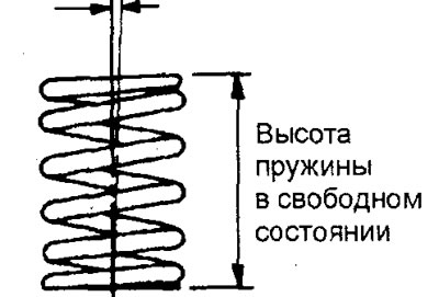
1. Measure the free height of the valve spring, and if it is less than the permissible value, replace the spring.
Table. Valve spring height.
| Engine | Nomin. | Limit. |
| 4G15-GDI | 49.1 mm | 48.6 mm |
| 4G15-MPI | 50.9 mm | 50.4 mm |
| 4G93-GDI | 44.8 mm | 43.8 mm |
| 4G93-MPI | 50.9 mm | 49.9 mm |
2. Measure the deviation of the valve spring axis from the perpendicular to the support surface. If the deviation exceeds the maximum permissible value, replace the spring.
Spring axis deflection:
nominal - 2° or less
maximum permissible - 4°
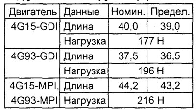
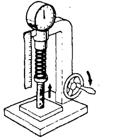
3. Using a spring tester, measure the force required to compress the spring to its installed length. If the force is less than the maximum permissible value, replace the spring.
Spring installation length (mm) under specified load (N):
Checking the valve guide bushing
1. Measure the clearance between the valve guide and the valve stem at several points along the length.
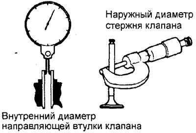
Clearance between valve guide and valve stem:
Nominal value:
- Inlet - 0.02 - 0.05 mm
Outlet:
- Engine 4G15 - 0.03 - 0.06 mm
- Engine 4G93 - 0.05 - 0.09 mm
Maximum permissible value:
- Inlet - 0.10 mm
- Outlet - 0.15 mm
Nominal valve stem diameter:
- Engine 4G15 - 5.5mm
- Engine 4G93 - 6.0 mm
Nominal internal diameter of valve guide bushing:
- Engine 4G15 - 5.52mm
- Engine 4G93 - 6.02mm
2. If the clearance exceeds the permissible value, replace the valve guide bushing or the valve, or both.
Repair
Valve seat restoration
1. Before performing valve seat reconditioning operations, check the clearance between the valve stem and the valve guide. If necessary, replace the valve guide.
2. Using a special tool (an end mill with a working chamfer angle of 30°, 45°, 60° or other), machine the valve seat to obtain the contact surface width and working chamfer angle that meet technical requirements.
Note: It is recommended to restore the valve seat geometry on machine tools.
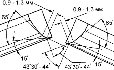
Engine 4G93
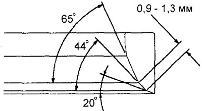
4G15-GDI engine - intake valve seat.
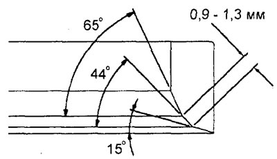
4G15-GDI engines - exhaust valve seat.
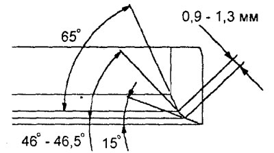
Engine 4G15-MPI.
3. After restoring the valve seat shape, the valve and valve seat should be lapped using lapping paste.
4. Check the amount of valve stem protrusion above the cylinder head surface (see the corresponding item in the paragraph "Checking the valve and valve seat").
Replacing the valve seat
Note: Valve seat replacement must be performed on machine tools.
1. Machine (cut) the inside of the valve seat to be replaced to reduce the thickness of its walls. Then remove the valve seat.
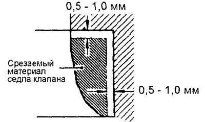
2. Ream the hole in the cylinder head to install a valve seat of increased diameter (repair size).
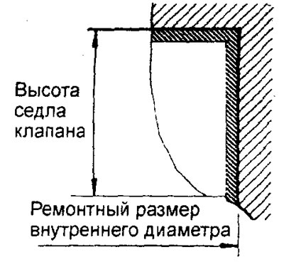
3. Before installing the valve seat, either heat the cylinder head to a temperature of approximately 250°C or cool the valve seat in liquid nitrogen to prevent mechanical damage (scoring) to the hole in the cylinder head when installing the seat.
4. Using a valve seat cutter, machine the seat to the required contact surface width and working chamfer angle (see the section "Restoring the valve seat").
Replacing the valve guide bushing
1. Using a special tool and a press, press out the valve guide bushing towards the cylinder head gasket surface.
2. Ream the hole in the cylinder head to install a valve guide bushing of increased diameter (oversize).
Note: Do not reinstall the valve guide of the same diameter after reaming the hole to oversize.
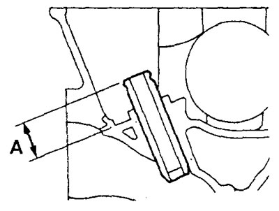
3. Press in a new valve guide bushing from the upper surface of the cylinder head so that its protrusion from the end to the seating surface of the valve spring seat is equal to "A" (see figure).
Nominal value "A":
- Engines 4G15 - 23.0 mm
- Engine 4G93-GDI - 19.0 mm
- 4G93-MPI Engine - 14.0mm
Note:
- Press in the guide bushings from the upper surface of the cylinder head (from the cover side).
- Please note the difference in the length of the guide bushings:
4G15 engines:
- for intake valve - 48.0 mm
- for the exhaust valve - 55.0 mm
Engines 4G93:
- for the intake valve - 45.5 mm
- for the exhaust valve - 50.5 mm
4. After installing the guide bushing, select a new valve for it and check that the valve moves freely, without sticking or excessive play.
5. After replacing the valve guide, check the contact patch of the valve with the seat. If the contact is incorrect, adjust the valve seat (grind the valve and the valve seat).
Valve repair
1. Grind the valve until all traces of carbon and scratches are removed.
2. Make sure that the working chamfer angle corresponds to the nominal value.
Attention:
- Valve grinding should be minimal.
- If the thickness of the valve plate after grinding is less than the maximum permissible value, replace the valve.
- After grinding, lap the valve and valve seat to ensure proper contact pattern.
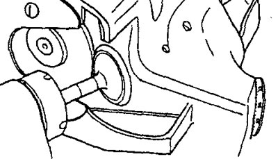
Lapping valve to seat
1. Apply a thin layer of lapping paste evenly to the valve seat surface.
Attention:
- Avoid getting lapping compound on the valve stem.
- First use medium-grain paste (grain size 120-150), then fine lapping paste (grain size over 200). - To ensure even application of the lapping paste, use a mixture of paste with a small amount of engine oil.
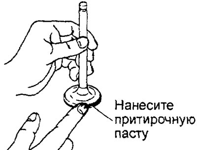
Table. Repair dimensions (internal diameters) of holes for valve guide bushing.
The material was copied from the website [MitsubishiMan.ru]
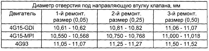
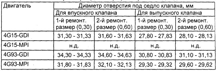
Table. Repair dimensions (diameters) of holes for valve seats.
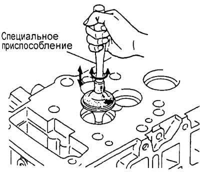
2. Press the valve against the seat several times, turning the valve little by little using a special device.
3. Wash off the grinding paste with kerosene.
4. Apply a thin layer of engine oil to the valve seat contact surface.
5. Check the valve seat contact patch. If necessary, restore or replace the valve seat.
Assembly
Installation of parts is carried out in the reverse order of removal.
When installing the parts, please pay attention to the following operations.
Note: Apply engine oil to all moving parts before installation.
1. Installing the oil seal.
a) Install the valve spring seat.
b) Using a special mandrel, install the oil scraper cap onto the valve guide sleeve.
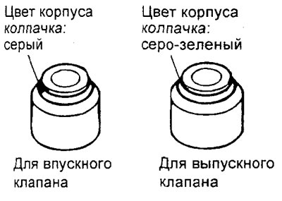
Note: for the 4G15-GDI engine, do not confuse the installation locations of the intake and exhaust valve oil seals; the oil seals are distinguished by color marks:
Symbolic mark on the cap:
- inlet valve - no
- exhaust valve - SD
Cap body color:
- inlet valve - grey
- exhaust valve - grey-green
Attention:
- Incorrect installation of the valve stem seal will result in increased oil flow through the valve guide.
- Do not install a used valve stem seal.
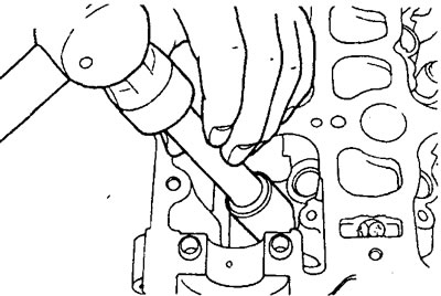
GDI engine
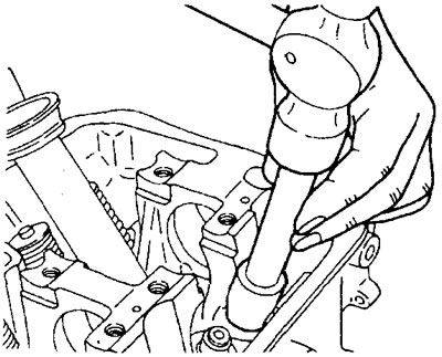
MPI engine
2. Installing the valve, valve spring and crackers.
a) Lubricate the valve stem with engine oil and insert it into the guide bushing. Check the freedom of movement of the valve.
Caution: Do not force the valve stem through the valve stem seal.
b) Install the valve spring in place so that the colored identification mark is located near the spring plate (top).
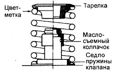
c) Use a puller to compress the spring and install the crackers into the groove of the valve stem.
Caution: If the spring is compressed excessively, the spring seat may rest against the oil seal and damage it.
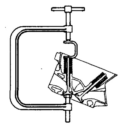
d) Check that the crackers are installed correctly after removing the puller.