



Contents: Removal and disassembly ⤓ Examination ⤓ Table. Checking the gap in the…⤓ Repair ⤓ Table. Color marks of oil scraper…⤓ Assembly and installation ⤓ Table. Selection of connecting rod…⤓ Table. Selection of connecting rod…⤓
Removal and disassembly
The parts are removed in the order of numbers shown in the figure "Removing the piston and connecting rod".
Note: The operation for removing the piston pin is described in the "Repair" subsection.
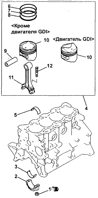
Removal the piston and connecting rod.1 - nut, 2 - lower connecting rod cover, 3 - lower connecting rod bearing shell, 4 - piston, connecting rod assembly, 5 - upper connecting rod bearing shell, 6 - compression ring No.1, 7 - compression ring No.2, 8 - oil scraper ring, 9 - piston pin, 10 - piston, 11 - connecting rod, 12 - bolt.
When removing parts, pay attention to the operation of removing the connecting rod cover.
a) Unscrew the nut, remove the connecting rod cover and remove the piston and connecting rod from the cylinder.
Caution: Be careful when removing the piston with the connecting rod assembly, do not let the connecting rod touch the cylinder surface and the crankshaft journal.
b) Apply the cylinder number to the side surface of the connecting rod to facilitate subsequent assembly.
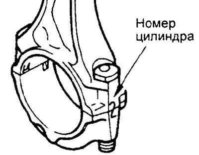
c) Lay out the removed parts (connecting rods, pistons, liners, etc.) in the order they correspond to the cylinder numbers.
Examination
Piston and piston pin
Caution: The piston and piston pin must be replaced as a set.
1. Replace the piston if there are scratches or scoring on its surfaces (especially on the thrust surfaces). Replace the piston if there are cracks.
2. Try to insert the piston pin into the piston hole using your thumb. You should feel resistance. Replace the pin if it enters the hole easily or there is significant play.
Piston rings
Note: If the piston is replaced with a new one, the piston rings must also be replaced with new ones.
1. Check the piston rings for damage, breaks or significant wear.
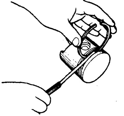
2. Measure the gap between the piston ring and the piston groove. If the gap exceeds the permissible value, replace the ring or the piston, or both parts.
Note:
- Before taking measurements, remove carbon deposits from all piston grooves.
- Measure the gap between the ring and the piston groove along the entire circumference of the ring
Clearance between the compression ring and the groove for it:
Nominal value:
- Ring No.1 - 0.03 - 0.07
- Ring No.2 - 0.02-0.06
- Maximum permissible - 0.1 mm
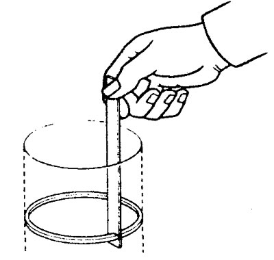
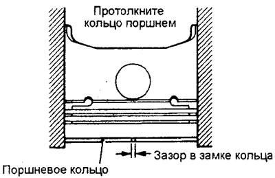
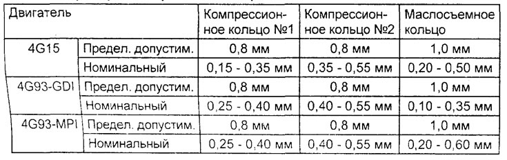
3. Install the piston ring into the cylinder bore. Move the ring with the piston as shown in the figure, this will allow the ring to stand at a right angle to the cylinder wall generatrix. Then measure the gap in the ring lock, and if the gap is greater than the permissible value (see table), replace the ring.
Connecting rod bearing shells
1. Checking the condition of the connecting rod bearing shells.
a) Visually inspect the surface condition of the connecting rod bearing shell (uneven contact, stripes, scratches, scoring, etc.). If defects are obvious, replace the connecting rod bearing shells.
b) If the defects (stripes and scoring) are significant, then check the corresponding crankshaft journals. If there are defects on the crankshaft journals, then replace the crankshaft.
2. Checking the clearance in the connecting rod bearing.
a) Measure the inner diameter of the connecting rod bearing and the outer diameter of the crankshaft journal, then determine the clearance in the connecting rod bearing.
Note: A plastic feeler gauge can be used to measure the connecting rod bearing clearance.
Nominal outside diameter of the crankshaft connecting rod journal:
- Engine 4G15 - 42.0 mm
- Engine 4G93 - 45.0 mm
Connecting rod bearing clearance:
- Nominal - 0.02 - 0.05 mm
- Maximum permissible - 0.10 mm
Table. Checking the gap in the piston ring lock.
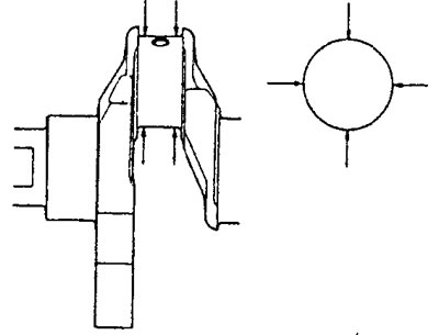
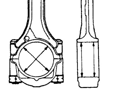
b) If the oil clearance exceeds the maximum permissible value, replace, if necessary, the connecting rod bearing shells or the crankshaft, or both parts.
3. Measuring the clearance in the connecting rod bearing using a plastic gauge.
a) Clean the crankshaft journals and liners from oil and dirt,
b) Cut a piece of plastic gauge to a length equal to the width of the bearing shell and place it parallel to the axis of the journal away from the oil passage hole.
c) Install the bearing shell and connecting rod cap and tighten the nuts.
Attention:
.
- Perform the tightening procedure for the connecting rod cap nuts in accordance with the special operation in the "Assembly and Installation" subsection.
- Do not rotate the crankshaft during the clearance measurement procedure
d) Remove the connecting rod cover and use the scale printed on the gauge packaging to determine the bearing clearance.
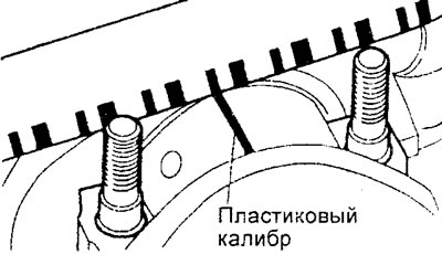
If the gauge is on the shaft journal.
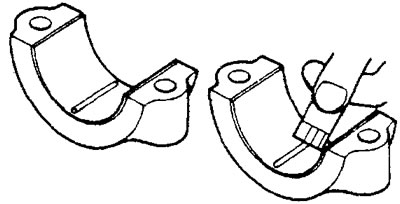
If the gauge is on the shaft bearing cover.
Connecting rod
1. Install the piston pin into the connecting rod if it was removed.
2. Using a special connecting rod tester "C" and a flat feeler gauge, check the bending and twisting of the connecting rod as shown in the figure.
Maximum permissible value (per 100 mm of length):
- bending - 0.05 mm
- twisting - 0.10 mm
Attention:
- Install the connecting rod in a special device "C" together with the installed upper and lower connecting rod bearing shells.
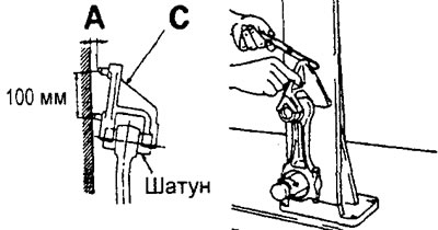
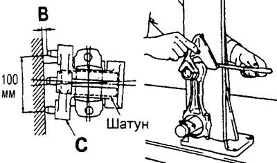
- Tighten the connecting rod cap mounting bolts in accordance with the special procedure in the "Assembly and Installation" subsection.
3. If the bending or twisting of the connecting rod exceeds the maximum permissible value according to technical requirements, replace the connecting rod assembly with the cover.
Repair
Selection of piston pin
Attention:
- If the engine cylinders have not been machined, then if it is necessary to replace the piston, select it so that the mark on its upper part corresponds to the cylinder size mark on the cylinder block according to the table provided.
- The piston size mark is located on the top of the piston.
| Cylinder size mark | Piston size mark |
| A | A |
| IN | no tag |
| WITH | WITH |
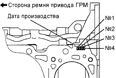
Rear part of the 4G15 engine cylinder block (surface for installing the cylinder head).
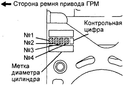
Rear part of the 4G93 engine cylinder block (surface for installing the cylinder head).
Replacing the piston pin
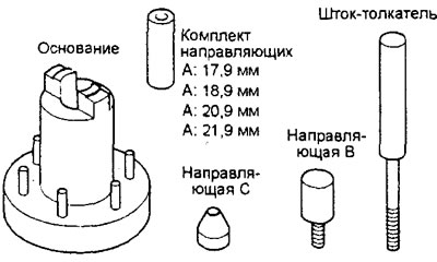
a) All necessary assembly and disassembly work on the connecting rod and piston group is carried out using a special tool (a set for assembling and disassembling piston assemblies), shown in the figure.
b) Insert the push rod into the piston from the side of the "front" mark (in the form of an arrow) applied to the bottom of the piston.
c) Install the piston and connecting rod on the base with the "front" marks facing up, as shown in the figure.
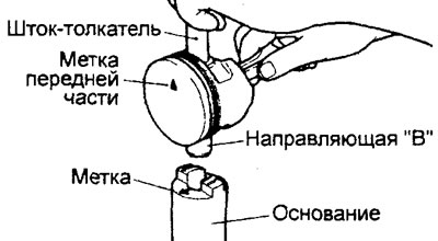
d) Using a press, remove the piston pin.
Note: To facilitate further assembly, keep disassembled parts separate from other similar parts.
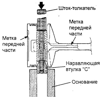
MPI engines.
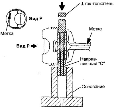
GDI engines.
d) Preparation of special tools:
- Measure the following values: A - length of the hole for the piston pin; B - distance between piston bosses; C - piston pin length; O - width of the upper connecting rod head.
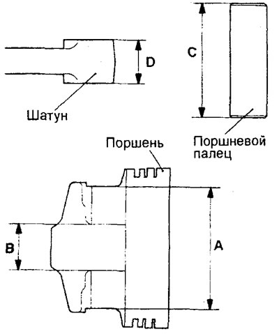
e) Determine the value of "L" using the following formula:
L = {(A-C) - (BD)}/2
g) Place the piston pin on the push rod and screw the guide sleeve "A" onto the end of the rod.
h) Place the piston and connecting rod together with the "front" marks facing up on the base of the fixture.
i) Apply engine oil to the piston pin surface.
k) Insert the unit (push rod with piston pin and guide sleeve "A" in assembly) with the sleeve into the combined hole of the piston and connecting rod (for the piston pin) from the side of the "front part" mark.
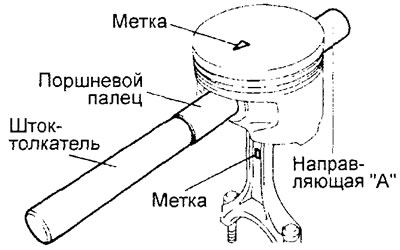
l) Screw the guide sleeve "B" into the guide sleeve "A" so that a distance equal to the value "L" measured in subparagraph "e" + 3 mm is formed between these guide sleeves.
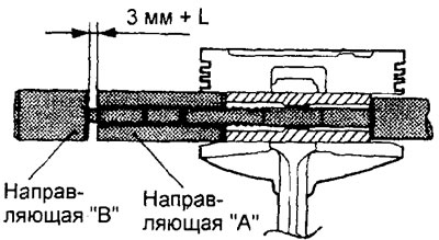
m) place the piston and connecting rod together with the "front" marks facing up on the base of the device.
n) Press the piston rod to install the piston pin. If the force developed during pressing is less than the nominal value, replace the piston with the piston pin assembly and/or the connecting rod.
Nominal pressing force:
- Engines 4G15 - 4900 - 14700 N
- Engines 4G93 - 4500 - 14700 N
Note: The piston pin is pressed in at room temperature.
Nominal outside diameter of piston pin:
- Engine 4G15 - 18.0 mm
- Engine 4G93 - 19.0 mm
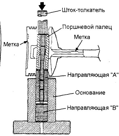
MPI engines
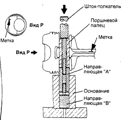
GDI engines.
Table. Color marks of oil scraper ring sizes.
| Engine | Nominal size (STD) | Repair size (0.50 mm) | Repair size (1.00 mm) |
| MPI | No | Blue | Yellow |
| GDI | No | Blue | Yellow |
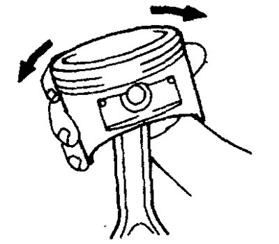
o) Check that the piston moves smoothly, without sticking.
Assembly and installation
Installation of parts is carried out in the reverse order of removal.
When installing the parts, please pay attention to the following operations.
1. Installing the oil scraper ring.
a) Install the oil scraper ring expander into the ring groove in the piston.
Note:
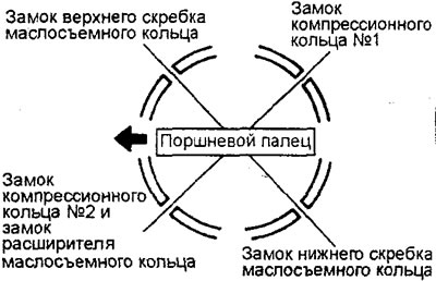
- Make sure the gaps in the scraper and expander locks are positioned as shown in the figure.
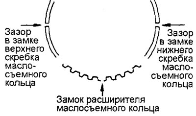
- New parts (expander and scrapers) are color coded according to their dimensions (see corresponding table).
b) Install the upper oil scraper ring.
To install the upper scraper, first install one end of the scraper into the piston groove, then insert the rest of the scraper with your finger as shown in the figure.
Caution: Do not use a piston ring expander. Unlike other piston ring parts, the oil ring scraper can break when expanded with an expander.
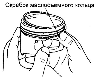
MPI engines
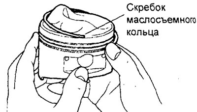
GDI engines.
c) Install the lower scraper of the low-removability ring in the same way as the upper one.
d) Check the correct installation of the three-piece oil scraper ring. When the oil scraper ring is installed correctly, it should rotate smoothly in any direction.
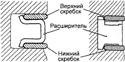
2. Installation of compression wheels No.1 and No.2.
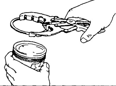
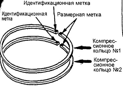
Using a compression ring expander, install compression rings #1 and #2 with the identification mark facing up.
Note:
- Each compression ring has a size and identification mark stamped on the ends of the ring. When installing, position the ring so that the mark is on top.
Identification mark:
4G15 engines:
- Ring #1 - 1R, 1T or T
- Ring #2 - 2R, 2T or T2
Engines 4G93:
- Ring No.1 - T
- Ring #2 - 2T or T2
- The size group of the compression ring is determined according to the table:
| Size | Size mark |
| Nominal (STD) | No |
| repair (0.50 mm) | 50 |
| repair (1.00 mm) | 100 |
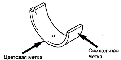
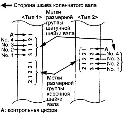
(Engine 4G 15) Selection of connecting rod bearing shells.
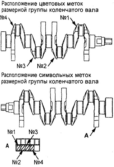
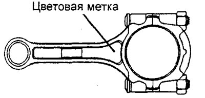
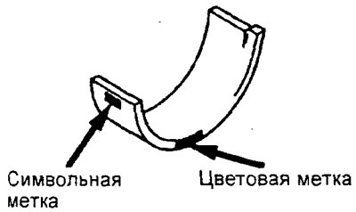
When replacing connecting rod bearing shells, select them according to the table provided in accordance with the size group (symbolic or color marks) of the crankshaft, the size group (color marks) of the connecting rod and the size group (symbolic or color marks) of the connecting rod bearing shells.
Nominal diameter of the lower connecting rod head hole - 45.000-45.015 mm
Please note: The crankshaft journal size group mark is only applied to the part supplied as a spare part.
4. (Engine 4G93) Selection of connecting rod bearing shells.
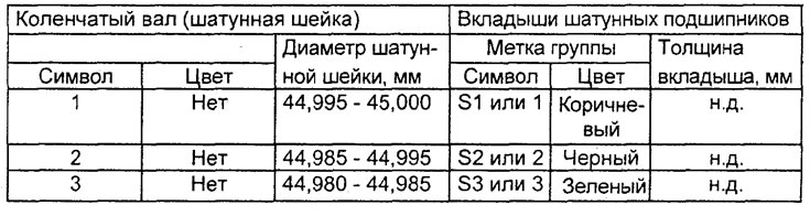
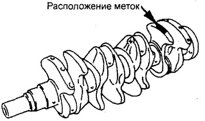
When replacing connecting rod bearing shells, select them according to the table provided in accordance with the size group (symbolic or color marks) of the crankshaft and the size group (symbolic or color marks) of the connecting rod bearing shells.
Nominal diameter of the lower connecting rod head bore - 48.000 - 48.015 mm
Please note: The crankshaft journal size group mark is only applied to the part supplied as a spare part.
Table. Selection of connecting rod bearing shells for the 4G15 engine.
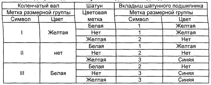
Table. Selection of connecting rod bearing shells for the 4G93 engine.
5. Installing the piston and connecting rod assembly.
a) Lubricate the surfaces of the piston and piston rings with engine oil.
b) Position the compression ring and oil scraper ring (expander and scrapers) locks as shown in the figure.
c) Turn the crankshaft so that the crankpin of the shaft is in the middle of the cylinder bore.
d) Use suitable protectors for the threaded elements of the connecting rod bolts before installing the piston with the connecting rod assembly into the cylinder bore. This will prevent damage to the working area of the crankshaft journals.
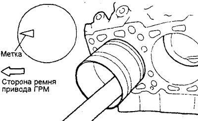
d) Using a special device for ring compression, install the piston with the connecting rod assembly into the cylinder bore of the block.
Caution: The piston with connecting rod assembly must be installed in the cylinder block so that the mark on the piston is directed towards the front of the engine (towards the timing belt).
6. Installing the connecting rod cap and checking the axial clearance of the lower connecting rod head.
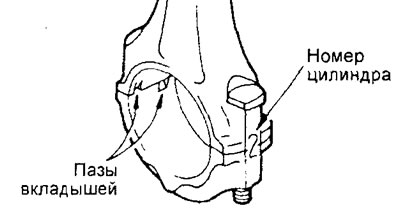
a) Align the corresponding caps with the corresponding connecting rods, taking into account the marks applied (cylinder number) and the method of fixing the bearings (bearing grooves). If a new connecting rod is installed without alignment marks, then locate the bearing grooves on the connecting rod and cap on the same side.
[Original source of information: mitsubishiman]
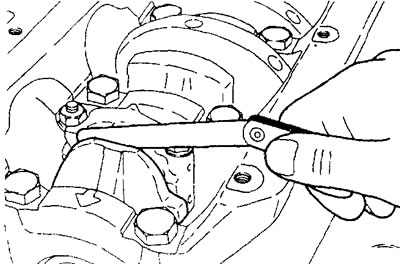
b) Using a flat feeler gauge, check the axial clearance of the lower connecting rod head.
Axial clearance:
- nominal - 0.10-0.25 mm
- maximum permissible - 0.40 mm
7. Tightening the connecting rod cap fastening nuts.
a) The connecting rod cap bolt and nut are tightened to the "yield point". Before installing the bolt, make sure that the bolt/nut thread is not deformed. The presence of deformation of the bolt-nut connection is checked by screwing the nut onto the bolt by hand to the end of the thread. If the nut is screwed onto the bolt by hand with difficulty, then the bolt thread is deformed and the bolt must be replaced.
b) Before installing the nut, apply a small amount of engine oil to the threaded parts of the nut and bolt, c) Screw the nuts onto the corresponding bolts by hand. Then tighten each nut individually to ensure that the connecting rod cap is seated correctly.
d) Tighten the cover mounting nuts alternately to the specified tightening torque.
Tightening torque:
- Engines 4G15 - 17 Nm
- Engines 4G93 - 20 Nm
d) Tighten the cover fastening nuts to an angle of 90 - 94°.
Attention:
- If the nut is turned at an angle less than 90°, the tightening of the cover fastening nuts will be insufficient.
- If the nut is turned to an angle of more than 94°, then unscrew the nut and repeat the tightening procedure from step "a".