
Removal and installation
Attention: on models with an additional passive safety system (SRS) before removing the steering gear, set the front wheels to the straight-ahead position and remove the key from the ignition. Failure to comply with these conditions may pueecmu damage the SRS coiled wire and cause the airbag to deploy unintentionally, resulting in serious injury.
− Before starting to remove parts, carry out the following operations:
- A) Remove the driver front airbag module.
- b) Drain the hydraulic fluid from the power steering hydraulic system.
- V) Remove a reception pipe of system of release.
- G) Remove the central longitudinal beam.
− Removal of parts is carried out in the order of numbers indicated in the figure "Removal of a cross beam of a forward suspension bracket".
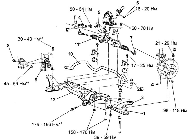 Removing the cross beam of the front suspension. 1 - lower arm and steering knuckle connection, 2 - self-locking nut, 3 - lower arm assembly, 4 - pressure hose connection, 5 - return hose connection, 6 - steering shaft and steering gear connecting bolt, 7 - tie rod end connection and steering knuckle, 8 - connecting bolt of the rear support of the power unit (remove the front suspension cross member assembly), 9 - rear support of the power unit, 10 - anti-roll bar, 11 - steering gear assembly, 12 - front suspension cross member.
Attention:
on vehicles with SRS:
- Symbol "*1" the figure shows the fastening elements that should first be pre-tightened, and the final tightening should be done after the power unit is completely lowered onto the supports with the vehicle horizontal.
- Connections marked with a symbol "*2" in the figure, first tighten only preliminary, and the final tightening should be done on an unloaded vehicle after lowering it onto the wheels.
− Pay attention to the following operations when removing parts.
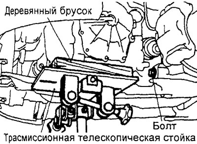
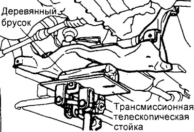
1. Removing the lower arm assembly.
Using the transmission telescopic stand, lift the: power unit, then remove the lower arm front connecting bolt to the front suspension cross member (From the left side).
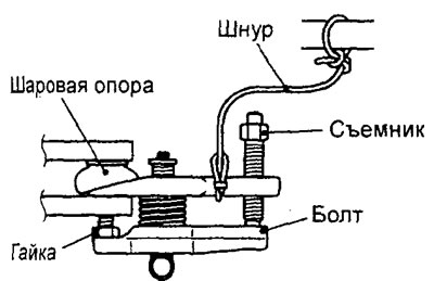
2. Disconnecting the tie rod end from the steering knuckle.
A) Install the ball joint puller as shown.
Attention:
- Just loosen the fastening nut on the ball joint pin at the steering knuckle, do not unscrew the nut completely. To avoid damage to the threads of the ball joint pin, disconnect it with the waste of a special tool.
- Tie the special tool with a cord so that it does not fall.
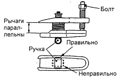
b) Turn the bolt and handle of the special tool so that its arms are parallel to each other. Finger-tighten the bolt and make sure the levers of the special tool are parallel to each other.
Note: When adjusting the position of the levers of the special tool, make sure that its handle is positioned as shown in the figure.
V) While tightening the special tool bolt with a wrench, disconnect the tie rod end.
3. Removing the cross beam of the front suspension.
Raise the cross member with the transmission telescopic strut and remove the cross member mounting bolts.
− Installation of parts is carried out in the reverse order of removal.
− Pay attention to the following operations when installing parts.
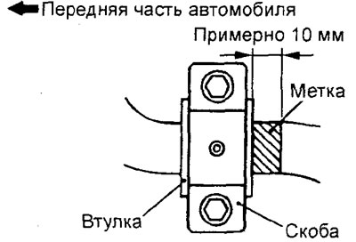
1. Installation of the anti-roll bar.
Align the color mark of the anti-roll bar with the right edge of the bushing.
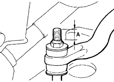
2. Installing a self-locking nut. Tighten the self-locking nut until the protrusion "A" corresponded to the nominal value.
Rated value "A" - 20.5 - 23.5 mm
- After completing the installation of the parts, perform the following operations:
- A) Establish the central longitudinal beam.
- b) Install the intake pipe.
- V) Install the driver front airbag module.
- G) Pour working fluid into the power steering hydraulic system.
- d) Bleed air from power steering hydraulic system.
- e) Check that there are no cracks or deformations on the protective covers.
- and) Check the middle position of the steering wheel when the front wheels are parallel to the longitudinal axis of the vehicle.
- h) Check and adjust the angles of the front wheels.
Examination
Check the front support cross member for cracks and deformation.