



Contents: Removal ⤓ Removal the crankshaft sprocket ⤓ Checking the automatic tensioner ⤓ Checking the timing belt ⤓ Installing the balance mechanism…⤓ Adjusting the tension of the balance…⤓ Installing the Crankshaft Position…⤓ Installing the timing belt tensioner…⤓ Installing the timing belt ⤓ Installation procedure ⤓ Adjusting the timing belt tension ⤓ Final operations ⤓
Removal
Remove the lower protective covers.
Raise the power unit to release the engine mount from the power unit load and remove the engine mount.
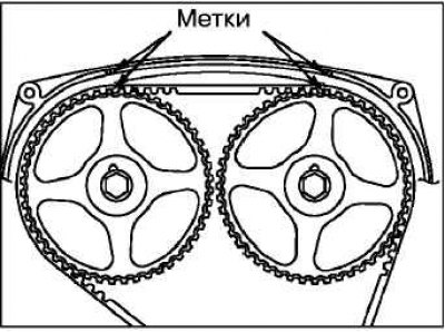
Rotate the crankshaft clockwise (right rotation) to align each timing mark and set the No.1 cylinder piston to TDC on the compression stroke.
Caution: If the accessory drive belt is reused, mark an arrow with chalk on the reverse (non-working) side of the belt indicating the direction of rotation.
Caution! Turn the crankshaft clockwise only.
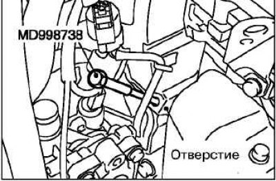
Insert the special tool (a ratchet or a 12.7 mm insert) into the special hole of the automatic tensioner of the drive belt of the auxiliary units in the assembly.
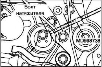
Attention! Screw in the special rod with a step of no more than 30° per second. If the rod is screwed in at full speed, it may become deformed due to the difficult movement of the tensioner rod.
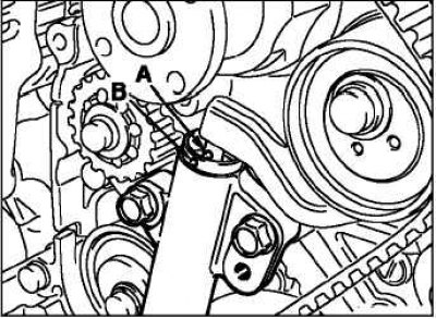 | 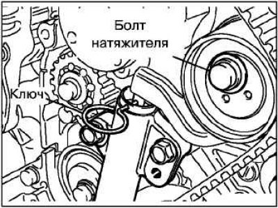 |
Slowly screw in the special rod, aligning hole "B" on the automatic tensioner body with hole "A" on the tensioner rod.
Insert a 2mm diameter wire into the hole in the automatic tensioner housing.
Loosen the tensioner roller adjusting bolt and remove the timing belt.
Removal the crankshaft sprocket
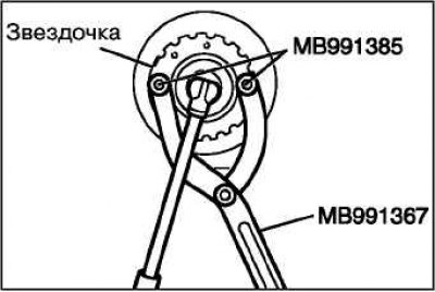
Using a special tool, secure the crankshaft from turning and unscrew the sprocket mounting bolt.
Caution: Make sure that the special tool is securely fastened and does not move.
Checking the automatic tensioner
Check the automatic tensioner for oil leaks, if any, replace it.
Also check the tensioner rod for wear and damage; replace the automatic tensioner if necessary.
Measure the amount of rod protrusion. If the value is not within the standard value, replace the automatic tensioner.
Standard value "A": 11 mm.
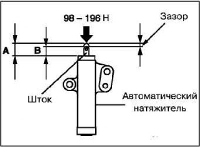
Press the tensioner rod against the cylinder block with appropriate force (98-196 N), then measure the rod stroke "B" as shown in the figure. If the rod stroke is beyond the specified value, replace the automatic tensioner.
Standard value "B": 1mm or less.
If the piston rod retracts without any resistance, replace the tensioner.
Check the smooth rotation of the tensioner roller.
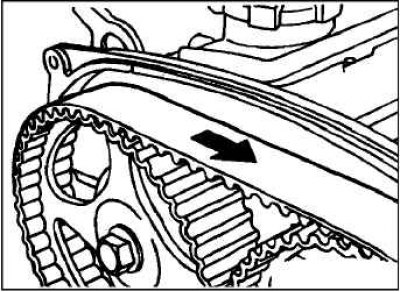
Caution! Before removing, if the balancer drive belt is reused, mark an arrow with chalk on the reverse (non-working) side of the belt indicating the direction of rotation.
Checking the timing belt
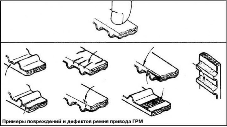
Check the belt for dirt or oil deposits. Replace if necessary.
Remove minor dirt from the belt with a dry cloth or cleaning paper.
Do not use solvents for these purposes.
When overhauling the engine or adjusting the belt tension, carefully inspect the belt. If any of the following defects are found, replace the belt with a new one.
Installing the balance mechanism drive belt
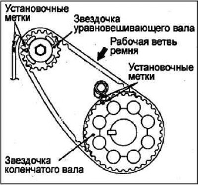
Check that the marks on the crankshaft sprocket and balance shaft sprocket are aligned with the corresponding timing marks.
Install the balancer drive belt onto the crankshaft sprocket and balancer shaft sprocket. Ensure that there is no slack in the belt.
Attention! Install the old belt so that the arrow on the back (non-working) side matches the direction of rotation of the belt.
Adjusting the tension of the balance mechanism drive belt
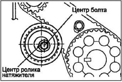
Install the balancer drive belt tensioner pulley so that its flange faces the front of the engine. Temporarily secure the tensioner pulley with the bolt so that the center of the tensioner pulley axis moves to the left and up from the center of the pulley mounting bolt.
Tighten the working branch of the belt by applying a force of 3±0.4 N·m to it.
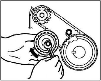
To do this, hold the balancer drive belt tensioner with your hand in the direction indicated by the arrow in the figure. Then fix the balancer drive belt tensioner in this position by tightening the fastening bolt.
Caution! When tightening the bolt, make sure that the tensioner roller does not turn together with the mounting bolt. If the tensioner roller turns, this will lead to excessive tension of the balancer drive belt.
Bolt tightening torque: 19 ±3 Nm.
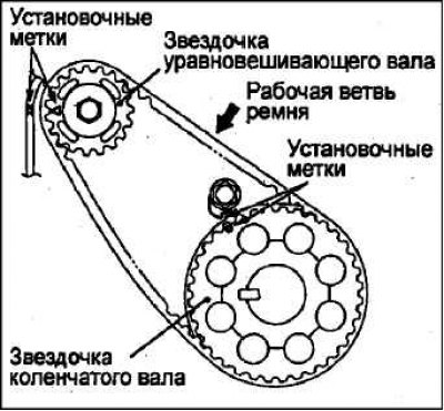
Turn the crankshaft 2 revolutions clockwise and set the piston of cylinder #1 to TDC of the compression stroke. Check the alignment of the timing marks.
Make sure that the deflection of the working branch of the balancer drive belt corresponds to the standard value. To do this, press with a force of 100 N in the center of the belt between the sprockets (while holding the roller from turning), as shown in the figure.
Standard deflection value: 5–7 mm.
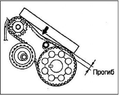
Adjust the belt deflection to match the standard value.
Installing the Crankshaft Position Sensor Rotor and Crankshaft Sprocket
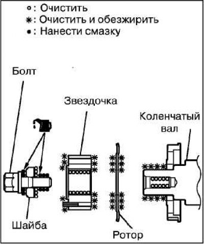
Clean and degrease the mating surface of the crankshaft and sprocket that contacts the crankshaft position sensor rotor.
Clean the crankshaft threaded hole, the end of the shaft, the sprocket mounting bolt washer and the surfaces in contact with it.
Install the crankshaft position sensor rotor and crankshaft sprocket, locating them as shown in the illustration.
Lubricate the mating surface (cone) of the crankshaft nose and the threads of the crankshaft bolt with a small amount of engine oil.
Before installing the crankshaft sprocket mounting bolt, you need to install the washer with the chamfered side facing the bolt.
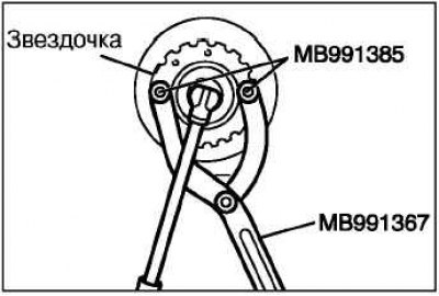
Using a special tool, secure the crankshaft sprocket or flywheel from turning. Install and tighten the crankshaft pulley mounting bolt.
Tightening torque: 167 Nm.
Installing the automatic timing belt tensioner (the automatic tensioner rod is in the fully extended position)
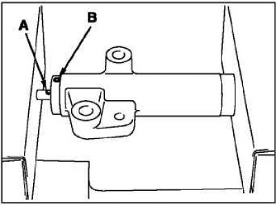
Use a press or vice to gently compress the automatic tensioner rod until hole "A" of the rod aligns with hole "B" in the tensioner cylinder.
Caution: If the compression speed of the piston rod is too fast, the piston rod may be damaged, so be careful and perform this operation slowly.
Attention! The automatic tensioner must be installed at a right angle to the surface of the vice jaws, without skewing.
Caution! Rapidly pressing the rod may damage it. Perform this operation gradually.
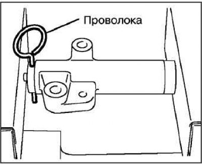
Once the holes are aligned, insert the dowel pin into them.
Install the automatic tensioner onto the engine and tighten the mounting bolts to the specified torque.
Tightening torque: 23±3 Nm.
Note: Do not remove the wire from the automatic tensioner
Installing the timing belt tensioner roller
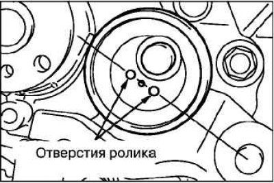
Install and temporarily secure the tensioner pulley so that the line passing through the centers of the pulley holes is located as shown in the illustration.
Installing the timing belt
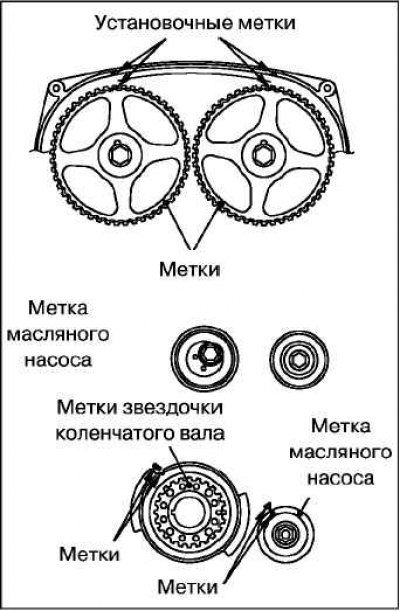
Check that the tensioner pulley and automatic tensioner are in the correct position. Make sure that the camshaft sprocket, crankshaft sprocket and oil pump sprocket marks are aligned with the corresponding timing marks (with the piston of cylinder #1 at TDC on the compression stroke).
Caution! If the timing marks are not aligned, the valves may be jammed by the piston when the camshaft sprocket is turned.
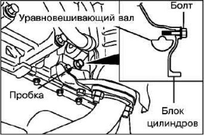
Remove the plug from the service hole on the cylinder block and insert a Phillips screwdriver (rod diameter 8 mm) into it.
If the screwdriver can be inserted to a depth of 60 mm or more, the timing marks are correctly aligned. If the screwdriver can only be inserted to a depth of 20–25 mm, turn the oil pump sprocket one revolution and align the timing marks again. Then check that the screwdriver is inserted to a depth of 60 mm or more. Leave the screwdriver inserted in the hole until the timing belt installation operation is completed.
Note: A bolt (M6 with a thread length of 10 mm and a total length of 45 mm) may be used to secure the balance shaft.
Install the timing belt onto the sprockets (do not allow the belt to sag between the sprockets or rollers).
Installation procedure
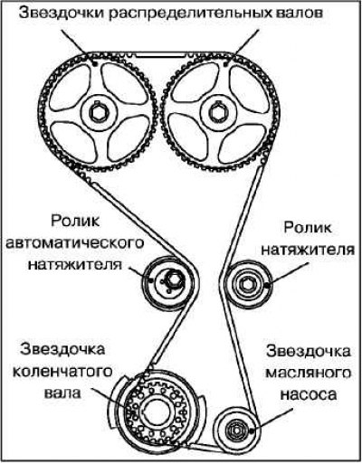
1. Crankshaft sprocket and timing belt tensioner roller.
2. Oil pump sprocket and timing belt guide roller.
3. Camshaft sprocket.
Attention! When installing the old belt, make sure that the arrow on the back of it matches the direction of rotation of the belt (clockwise).
Note: Before installing the timing belt onto the camshaft sprockets, ensure that all sprocket marks are aligned with the corresponding timing marks.
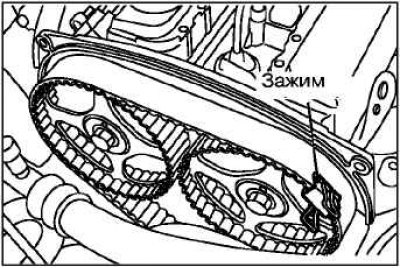
Using a strap clamp or wire, secure the timing belt to the exhaust camshaft sprocket in the position shown in the illustration.
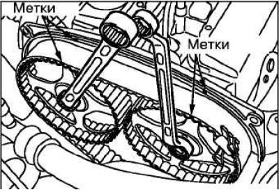
Note: Before installing the timing belt onto the camshaft sprockets, make sure the sprocket marks are aligned with the corresponding timing marks. Using two wrenches, install the timing belt onto the intake camshaft sprocket.
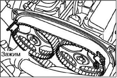
Perform the operation by installing a band clamp or wire on the intake camshaft sprocket in the position as shown in the figure.
Install the timing belt onto the belt tensioner roller.
Remove the clamps that secure the camshaft sprockets.
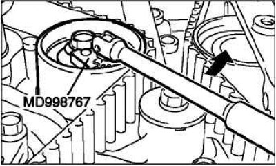
Move the tensioner pulley so that its holes are horizontal. Then lightly press the tensioner pulley against the timing belt and temporarily tighten the bolt before adjusting the belt tension.
Adjusting the timing belt tension
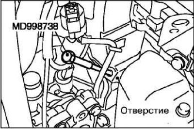
Screw the special rod into the hole of the attachment bracket.
Caution! Screw in the special rod by hand, as using a special tool may damage the wire inserted into the automatic timing belt tensioner.
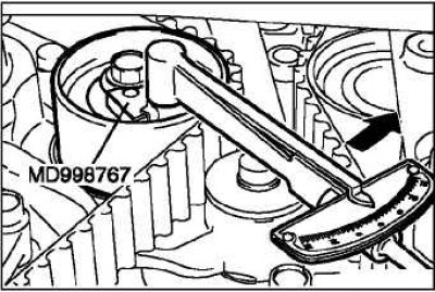
Slowly screw in the special rod until the position where the wire inserted into the automatic tensioner moves easily.
Turn the crankshaft 1/4 turn counterclockwise, then turn the crankshaft clockwise to align the timing marks.
Loosen the tensioner roller mounting bolt and, using a special tool and a torque wrench, apply torque to the tensioner roller (tighten the belt).
Standard value: 3.5 Nm.
After this, holding the tensioner roller from turning, tighten the mounting bolt to the nominal tightening torque.
Tightening torque: 48±5Nm.
Caution: When tightening the mounting bolt, make sure that the tensioner roller (or its shaft) does not turn together with the bolt.
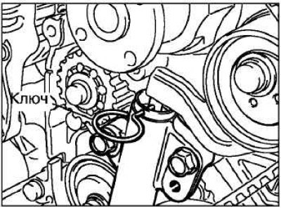
Remove the wire or pin from the automatic tensioner.
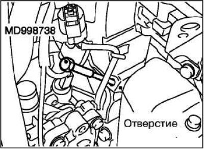
Remove the special rod from the hole in the attachment bracket and install the plug.
Turn the crankshaft clockwise two revolutions and align the timing marks.
Wait for about 15 minutes and check that the wire can be easily inserted into the automatic tensioner and removed from it. If this does not happen, check that the protrusion value of the automatic tensioner rod is within the nominal values.
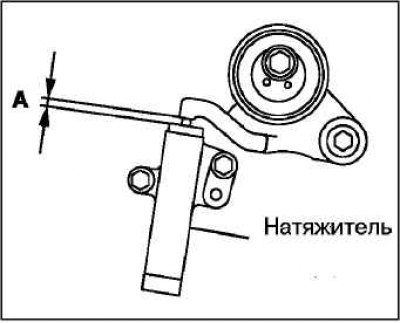
Standard value A: 3.8-4.5mm.
If the piston rod protrusion value is not within the nominal value range, repeat the operations again, then check that the marks on all sprockets are aligned with the corresponding installation marks.
Final operations
Install the engine mount.
Install the lower guards.
Adjust the tension of the attachment drive belt.