
Injector test
1. Disconnect the connector from the injector.
2. Measure the resistance between the connector pins.
The nominal value is 13-16 ohms at 20°C.
3. Connect the injector connector.
Checking the shape of the spray jet and the tightness of the nozzle
1. Relieve residual pressure in the fuel line to prevent fuel splashing.
2. Remove the nozzle.
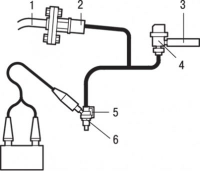
Pic. 7.16. Special tool for checking the spray pattern and the tightness of the nozzle: 1 - high pressure fuel hose; 2 - adapter; 3 - fuel return hose; 4 - fuel pressure regulator; 5 - nozzle; 6 - special clamp
3. Assemble the special tool (injector test kit), adapter, pressure regulator and clamps as shown in fig. 7.16.
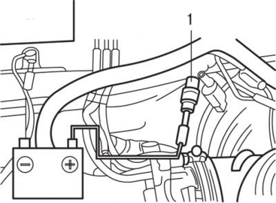
Pic. 7.9. Connecting the service connector (1) fuel pump to battery positive to test fuel pump operation
4. To turn on the fuel pump, connect the wire (with connectors «crocodile») from the positive terminal of the battery to the terminal of the black service connector of the fuel pump (see fig. 7.9).
5. Activate the nozzle and check the quality of fuel atomization from the nozzle.
The condition of the nozzle is satisfactory if the nozzle gives normal atomization.
6. Disconnect the wires from the injector connector pins and check the tightness of the atomizer and injector locking needle.
Norm: 1 drop or less for a minute.
7. Connect the wires from the battery terminals to the injector terminals, not including the fuel pump. Then, after stopping the spray of fuel from the injector, disconnect the special tool and reinstall the injector.
Removing
1. Disconnect a wire from the negative plug of the storage battery.
2. Relieve fuel pressure (to prevent fuel splashing).
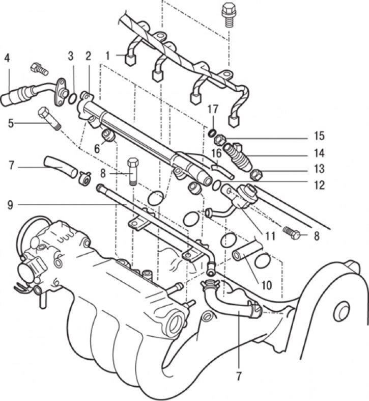
Pic. 7.17. Nozzles: 1 - nozzle connector; 2 - fuel rail; 3 - annular gasket; 4 - connection of the flange of the high pressure fuel hose with the fuel rail; 5 - bolt (10–13 Nm); 6 - sealing gasket; 7 - fuel return hose; 8 - bolt (9 Nm); 9 – a tube of return of fuel; 10 – a hose of system of compulsory ventilation of a crankcase (PCV); 11 - fuel pressure regulator; 12 - annular gasket; 13 - sealing gasket; 14 - nozzle; 15 - sealing sleeve; 16 - vacuum hose; 17 - ring gasket
3. Disconnect the hose of the forced crankcase ventilation system (PCV) 10 (pic. 7.17).
4. Disconnect the injector connectors 1.
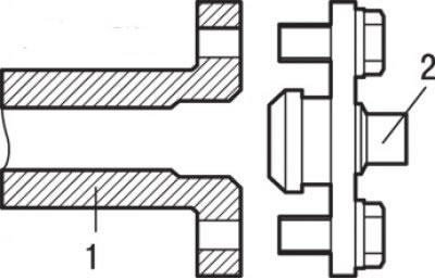
Pic. 7.18. Flange connection (1) high pressure fuel hose with fuel rail (2)
5. Turn away bolts and disconnect a flange of a fuel hose of a high pressure from a fuel stage (pic. 7.18).
6. Remove O-ring 3 (see fig. 7.17).
7. Loosen the clamps and remove the fuel return hose 7.
8. Disconnect the vacuum hose 16.
9. Turn away bolts and remove a regulator of pressure of fuel 11.
10. Remove O-ring 12.
11. Turn away bolts and remove a fuel rail 2 together with the nozzles established on it.
Attention! Be careful not to drop the injectors when removing the fuel manifold.
12. Loosen the clamp and remove the fuel return pipe 9.
13. Remove gaskets 6 and 13.
14. Being careful, remove nozzles 14.
15. Remove the O-rings 17 from the injectors.
16. Remove sealing sleeves 15.
Installation
Installation is carried out in the reverse order of removal, taking into account the following.
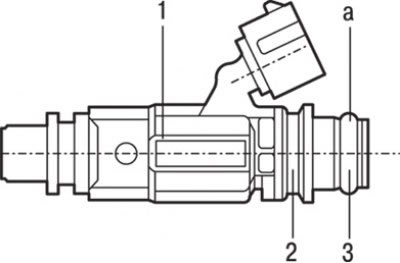
Pic. 7.19. Nozzle: 1 - nozzle; 2 - sealing sleeve; 3 - annular gasket; a - the place of lubrication
1. Apply some clean engine oil to the O-ring before installation (pic. 7.19).
Attention! Be careful not to let oil get into the fuel manifold.
2. Turning the injectors, high pressure fuel hose and fuel pressure regulator left and right, carefully install the fuel rail so as not to damage the O-rings.
3. After installation, check if the flange of the high pressure hose in the fuel rail turns smoothly.
4. If the fuel hose flange does not turn smoothly in the fuel manifold, the O-ring may be pinched. In this case, disconnect the high pressure hose from the fuel rail, insert it back into the fuel rail and check that the hose flange turns smoothly.
5. Tighten the high-pressure fuel hose flange bolts to the prescribed tightening torque, and the fuel pressure regulator bolts to 9 Nm.