



Cooling system diagram
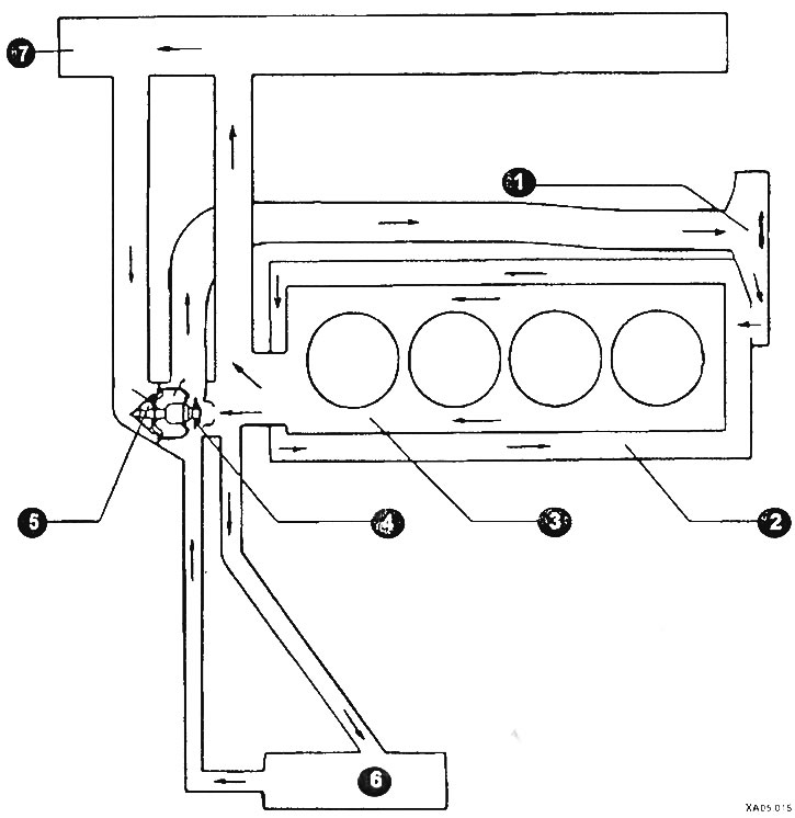
1 - coolant pump; 2 - pipeline; 3 - cylinder block; 4 - thermostat; 5 - thermostat housing; 6 - heater radiator; 7 - radiator.
All vehicles are equipped with a thermostatically controlled circulating coolant cooling system. A water pump mounted to the front of the engine circulates coolant through the engine. Coolant flows around each cylinder toward the rear of the engine. Cast coolant passages direct the coolant around the intake and exhaust ports, behind the spark plugs, and in close proximity to the exhaust valve guides.
The thermostat is located at the rear of the engine. During warm-up, the closed thermostat prevents coolant from passing through the radiator. As the engine reaches normal operating temperature, the thermostat opens and allows hot coolant to pass through the radiator, where it is cooled before returning to the engine.
In the cooling system at the operating temperature there is an excess pressure of 1.2-1.5 bar, which significantly increases the boiling point of the coolant above 100°C. At the same time, a certain reserve is provided. The engine can heat up to a temperature above 100°C without the risk of boiling of the liquid in the cooling system. To maintain the correct pressure in the system, the radiator is equipped with a cap with a safety valve (1.2-1.5 bar) and a vacuum valve (0.03-0.13 bar). The vacuum valve lets in air when the coolant decreases in the regional valve during cooling.