
Attention! On vehicles equipped with the SRS Supplemental Restraint System, before removing the airbag module, learn the safety precautions for servicing the SRS system.
Removing
To remove the steering wheel and steering shaft, perform the following steps in sequence.
1. Disconnect a wire from the negative plug of the storage battery.
2. Remove the bottom panel of a combination of devices.
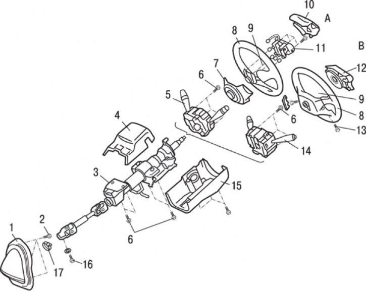
Pic. 13.8. Steering wheel and steering shaft: A - cars not equipped with an SRS system; B - cars equipped with the SRS system; 1 - protective cover assembly; 2 - bolt (10 Nm); 3 – a steering shaft in gathering; 4 – the top casing of a steering column; 5 - steering column combined switch (vehicles without SRS); 6 - bolt (25 Nm); 7 – the bottom cover of a steering wheel (vehicles without SRS); 8 - steering wheel; 9 - nut (42 Nm); 10 – an overlay of the switch of a sound signal (vehicles without SRS); 11 – sound signal switch; 12 - airbag module; 13 - bolt (7.5 Nm); 14 - stalk combined switch assembly with a clock spring; 15 – the lower casing of a steering column; 16 - bolt (17 Nm); 17 - collar
3. Remove trim 10 (pic. 13.8) horn switch (vehicles without SRS).
4. Disconnect the wires and remove the airbag module 12 (cars with SRS).
5. Disconnect the wires and remove the horn switch 11 (vehicles without SRS).
6. Turn away a nut of fastening of a steering wheel, mark mutual position of a steering wheel and a shaft with tags and, using special adaptation МВ 990803, remove a steering wheel.
7. Remove the bottom cover 7 of the steering wheel (vehicles without SRS).
8. Remove the top casing 4 of a steering column.
9. Remove the bottom casing 15 of a steering column.
10. Disconnect the wires and remove the stalk combined switch 5 (vehicles without SRS).
11. Disconnect the wires, unscrew the three screws and remove the stalk combined switch 14, complete with clock spring.
12. Turn away a bolt in the bottom part of a steering shaft and remove a steering shaft 3 in gathering.
13. Remove clamp 17.
14. Remove protective cover 1 as an assembly.
Installation
Installation is carried out in the reverse order of removal, taking into account the following.
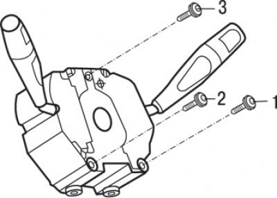
Pic. 13.9. The sequence of tightening the screws for fastening the stalk combined switch assembly with a clock spring
1. Install the stalk combination switch with clock spring assembly and secure with two screws by tightening them in the sequence shown in fig. 13.9.
2. Establish the bottom panel of a combination of devices.
3. Check up average position of a steering wheel and forward wheels.