



Contents: Examination ⤓ Adjustment ⤓ Replacement ⤓ Models 1.5L, 1.8L, 2.0L and 2.4L ⤓ 3.0L DOHC, Galant 3.0L SOHC and 3.5L…⤓ Diamante Models 3.0L SOHC ⤓
Examination
1. Drive belts are located at the front of the powertrain and play a vital role in the operation of the engine and many other vehicle systems. Over time, belts wear out and should be inspected regularly as part of the vehicle's routine maintenance schedule to avoid serious engine failures that can be costly to repair.
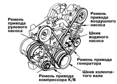
2. The number of drive belts used on a particular vehicle model depends on the vehicle's auxiliary equipment. Belts are used to drive the generator, steering and water pumps, and the air conditioning compressor. Depending on the nature of the pulley arrangement, one belt can drive more than one unit.
3. Turn off the engine, open the hood and locate the drive belts.
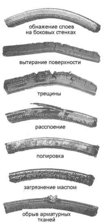
4. Using a flashlight, feel the belts along their entire length with your fingers, checking for cracks and delamination. The belts must not have any abrasions, polished areas or other obvious defects. Inspect the belts from both sides, twisting them. Defective belts must be replaced without fail. Check the condition of the ribs on the underside of the belts - they must be of the same depth and show no signs of deformation.
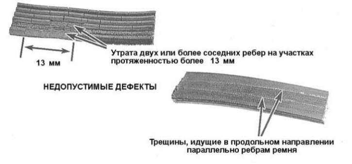
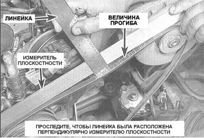
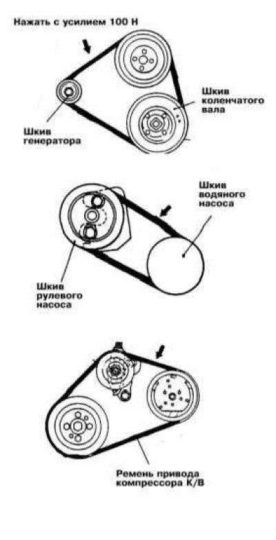
5. The belt tension force can be assessed by pressing it with your thumb on the area in the middle between two adjacent pulleys. The pressure should be firm enough. The parameter characterizing the belt tension force is the value of its deflection when pressed. As a rule, if the pulleys are spaced from 180 to 280 mm apart, the deflection should be 6.4 mm, a distance between pulleys of 305÷405 mm corresponds to a deflection of 12.5 mm for a V-belt, and 6.4 mm for a V-belt.
Adjustment
1. Excessive tensioning of the drive belt can lead to premature failure of the pulley bearings of the relevant units, while, on the other hand, too little tension leads to rapid wear of the belt itself. Regularly check the tension of the drive belts of all auxiliary units installed on the vehicle.
2. As a rule, the adjustment of the belt tension force (loosening/strengthening) is carried out by shifting the belt-driven auxiliary unit/tensioner assembly in the appropriate direction.
The article is based on data from the website: mitsubishiman
3. Typically, each of the drive belts used on the engine has one component, which is secured by means of an axle/stop bolt and an adjusting bolt. The axle/stop bolt is loosened, then the adjusting bolt is turned in the appropriate direction.
4. To reduce the belt tension, the component should be moved towards the engine and vice versa. After completing the adjustment, ensure that the bolts are securely tightened. To move some attachments, you will have to use a lever - be extremely careful not to damage the driven device.
Replacement
Models 1.5L, 1.8L, 2.0L and 2.4L
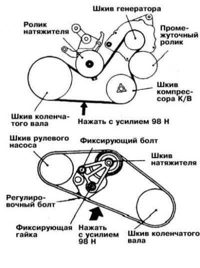
The diagram of the auxiliary drive belt routing on these models is shown in the illustration.
Generator drive belt
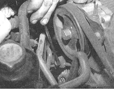
1. Loosen the generator mounting nut, then loosen the lock bolt.
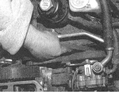
2. By turning the adjusting bolt counterclockwise, loosen the belt tension, remove the belt from the pulleys and remove it from the engine compartment.
If the removed belt is to be reused, the direction of its rotation should be marked with chalk - this parameter must be observed during installation.
3. Place the new belt on the appropriate pulleys and, by turning the adjusting bolt clockwise, adjust its tension (see above).
4. After completing the adjustment, tighten the lock bolt and fixing nut securely.
Steering pump drive belt
1. Remove the alternator belt (see above).
2. Loosen the steering pump adjusting bolts.
3. Loosen the retaining bolt on the rear side of the pump assembly support bracket.
4. Press the pump towards the engine and remove the belt.
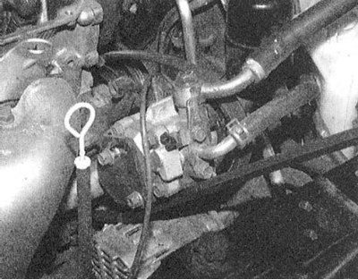
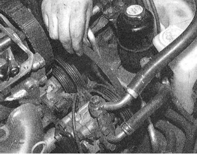
5. Place the new belt on the appropriate pulleys.
6. By pressing the pump assembly away from the engine, achieve the required belt tension force (see above).
7. Tighten the adjusting bolts securely, then tighten the locking bolt on the back of the pump support bracket.
8. Install the alternator belt in place (see above).
A/C compressor drive belt
1. Loosen the tensioner pulley and remove the A/C compressor drive belt from the engine.
2. Installation is carried out in reverse order.
3.0L DOHC, Galant 3.0L SOHC and 3.5L models
Generator and compressor drive belt K/V
1. The diagram of the auxiliary drive belt routing on these models is shown in the illustrations (see above).
2. Jack up the vehicle and place it on supports. If equipped, remove the crankcase protection elements.
3. Loosen the tensioner pulley locking nut and turn the adjusting bolt to loosen the belt tension.
4. Remove the belt from the pulleys and remove it from the engine.
5. Place the new belt on the crankshaft, generator and (if equipped) compressor pulleys and place it under the tension and intermediate rollers.
6. Turn the tensioner adjusting bolt to achieve the required belt tension (see above).
7. Tighten the lock nut securely.
8. If removed, reinstall the crankcase protection elements and lower the vehicle to the ground.
Steering pump drive belt
1. Disconnect the negative battery cable and wait at least 90 seconds before proceeding with the procedure to deactivate the airbags.
If your car stereo system is equipped with a security code, make sure you have the correct combination to activate the audio system before disconnecting the battery!
2. Jack up the car and place it on supports. Remove the crankcase protection elements.
3. Remove the generator/compressor drive belt.
4. Lower the vehicle to the ground and remove the cruise control pump tie rod assembly.
5. Route the power steering hose under the oil reservoir.
6. Loosen the tensioner pulley retaining bolts, then remove the steering pump drive belt from the engine.
7. Place the new belt on the appropriate pulleys.
8. Insert the drive reinforcement collar of the socket wrench (or other suitable tool) into the hole in the end of the tensioner pulley bracket and, by pressing the latter assembly, achieve the required belt tension force (see above).
9. Tighten the fixing bolts.
10. Jack up the vehicle and place it on supports. Install the alternator/compressor drive belt in place.
11. Reinstall the engine protection elements and lower the vehicle to the ground.
12. Connect the negative cable to the battery.
Diamante Models 3.0L SOHC
1. Disconnect the negative cable from the battery.
If your car stereo system is equipped with a security code, make sure you have the correct combination to activate the audio system before disconnecting the battery!
2. Loosen the lock bolt on the crankshaft belt tensioner pulley.
3. Turn the pulley adjusting bolt to loosen the belt tension.
4. Remove the belt from the pulleys and remove it from the engine.
5. Loosen the lock nut on the alternator/steering pump drive belt tensioner pulley.
6. Turn the adjusting bolt to loosen the belt tension and remove the belt from the engine.
7. Always install the alternator/steering pump drive belt first and then the A/C compressor belt.
8. Turn the adjusting bolts until the required tension is achieved on both belts (see above). Then tighten the retaining fasteners (the alternator/steering pump drive belt tensioner pulley nut should be tightened to 50 Nm).
9. Connect the negative cable to the battery.