
Disassembly
Drain engine oil (if not leaked).
Remove all attachments.
Remove the clutch. When loosening the mounting bolts, fix the flywheel with a large screwdriver. Mark the relative position of the clutch and flywheel. Loosen the mounting bolts evenly and gradually.
After loosening the alternator mounting bolts, remove the drive belt, alternator and belt tensioner bar.
Remove the power steering pump drive belt.
Remove the cooling fan.
Remove the top timing belt cover
After unscrewing the bolts, remove the cylinder head cover
Secure the crankshaft from turning and remove the four pulley bolts. Remove adapter flange and pulley.
Turn away bolts, remove the bottom cover of a gear belt.
Turn the crankshaft so that the piston of the 1st cylinder is at TDC on the compression stroke. To do this, install the crankshaft so that the alignment mark on the camshaft wheel (1) turned out to be the opposite of risk (2) on the fuel pump bracket. Make sure that the rocker arms of the valves of the first cylinder move freely. Otherwise, tighten the crankshaft one turn.
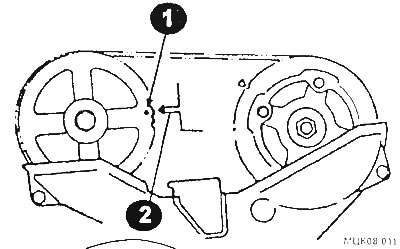
Mark the position of the belt on the wheel with a mark.
Valve springs
Check the length of the springs in the free state and under load. If the length does not match the required value, replace the springs.
Check the deflection of the springs from the vertical. If the backlash on length of a spring exceeds 1,6 mm replace a spring.
When assembling, the springs are installed so that the color marking is facing up. New springs must have the same markings as those being replaced.
Valves
Remove valve stem seals from valves and guide bushings.
Check the condition of the valves and guide bushings. Clean the inside of the guide bushing with a rag soaked in gasoline.
Check clearance between valve and guide sleeve. For this:
- After installing the dial indicator, remove the valve from the end of the sleeve by 30 mm.
- Place the indicator foot against the valve head and set the indicator needle to zero.
- Rock the valve in the sleeve.
- If the reading is greater than 0.20 mm, the valve or bushing must be replaced.
The guide bushings are pressed out by a mandrel from the side of the rocker rollers.
ATTENTION: Guide bushings are pressed into the diesel head at room temperature.
Press in new bushings. Spare parts are supplied with repair sleeves with a diameter increased by 0.05; 0.25 and 0.50 mm (they are marked «5», «25» And «50» respectively). Before pressing the holes for the guide bushings in the cylinder head, expand to the diameter of the repair bushing. When replacing bushings, keep in mind that the intake and exhaust valve guides may have different lengths.
Before pressing out, measure the height to which the guide bush protrudes. Press the new bushing in from the side of the combustion chamber so that the protrusion of the new bushing is 1 3.7-14.3 mm.
ATTENTION: On the 4D65 diesel engine, the valve guides are pressed out and pressed in at room temperature of 20°C. When replacing the guide bushings, the valve seats are ground, regardless of their condition.
Valve seats
Check the condition of the valve seats. Remove minor defects with a hand cutter. Replace valve seats if necessary. Repair valve seats are supplied as spare parts, the diameter of which is increased by 0.3 and 0.6 mm, the holes for the seats in the cylinder head should be bored to the appropriate size of the seat.
Sand the seat after replacement. After that, lap the valve.
Clean the cylinder head after lapping. Especially carefully clean the bores of the guide bushings.
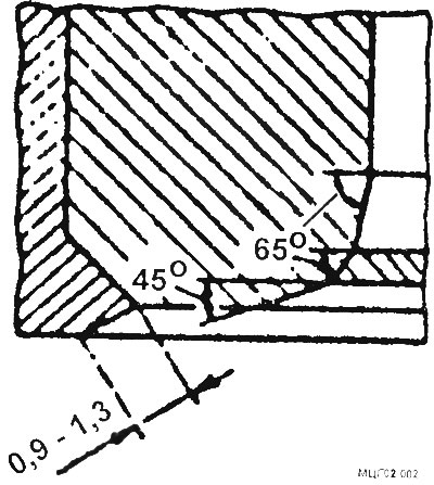
Check the width of the chamfer of the valve seat, which for intake and exhaust valves should be within 0.9-1.3 mm, the grinding angles of the seat should be as shown in the figure.
Valves
Replace valves with bent stems or stems showing burn marks. Repair of valves by grinding or turning the rod is not allowed. If signs of wear are found on the thrust surfaces of the rocker arms, it is allowed to remove material from the end face of the valve up to 0.5 mm. If the end of the valve is worn out, then check the condition of the rocker arms. Carefully inspect the valves, check for cracks on the chamfers of the valves, signs of uneven wear. Check for cracks on the valve necks.
Small defects in the valve head can be removed by lapping. If significant defects are found, the valve head is ground. After grinding and giving a chamfer at an angle of 45°, the height of the edge of the inlet valve must be at least 0.7 mm, otherwise the valves must be replaced.
Check the clearance between the bushing and the valve using a dial gauge by inserting the valve into the guide bushing. To do this, install a dial indicator, raise the plate from the end of the sleeve by 30 mm. Place the indicator foot against the valve head and zero out, shake the valve in the sleeve and read the indicator reading. If the reading is greater than 0.20 mm, the valve or bushing should be replaced. Make your final decision after checking the valve stem diameter. If the stem diameter is less than the required value, then the valve must be replaced.
Rocker arms
Check axles and rocker arms for wear and damage. Check the diameter of the rocker shaft and the inner diameter of the rocker arm. The difference between these diameters (the gap should not exceed 0.01-0.05 mm. Otherwise, the roller and rocker should be replaced. If wear is detected on the bearing surfaces of the rocker arms, grinding of the bearing surfaces is allowed. The allowable removal of metal during rocker grinding should not exceed 0.5 mm.
A heavily worn rocker surface makes valve adjustment much more difficult. If after the material of the bearing part of the rocker arm is ground 0.5 mm and an uneven surface is still observed, then replace the rocker arm.
Install the camshaft in bed and tighten the six mounting bolts by hand.
Put on the axis of the rocker arms and springs.
Install the axle assembly with rocker arms in the camshaft bearing journals and tighten the bolts.
Tighten the camshaft cover bolts and the shaft mounting bolts to the specified torque. Check the correct installation of the springs.
Press the camshaft oil seal into the bore at the front of the cylinder head. The seal must be flush with the surface of the cylinder head.
Lubricate the seal lips with grease. Lubricate the center groove of the segment plug with sealant and install the plug in place.
Further assembly is carried out in the reverse order.
Cylinder head
Clean the cylinder head, remove the remnants of the gasket material from the contact planes of the head.
Remove carbon deposits from combustion chambers. Run and clean all threaded holes. Check the deformation of the contact surface of the head. If the deviation from the plane is less than the limit (0.10 mm), then the head should be reground. If the deviation from the plane exceeds 0.10 mm, at least in one place, then the cylinder head should be replaced.