



Contents: Removal ⤓ Examination ⤓ Automatic timing belt tensioning…⤓ Installation ⤓ Adjusting the timing belt tension ⤓ Rod protrusion (A) from the…⤓
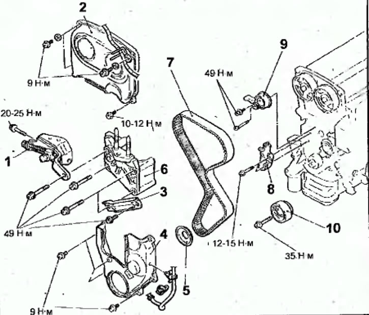
Fig. 2.41. Timing drive toothed belt: 1 - generator tension bar; 2 - Upper front timing belt cover; 3 - Power steering pump support bracket; 4 - lower front toothed belt cover, 5 - flange; 6 - Engine support bracket; 7-toothed timing belt for gas distribution mechanism drive; 8 - automatic belt tensioning mechanism; 9-pulley and belt tensioner lever; 10-idler pulley
Removal
- Disconnect the cable from the negative battery terminal.
- Remove the bolts and remove the cover from the engine.
- Remove the lower engine splash shield.
- Remove the crankshaft pulley of the poly V-belt drive.
- Remove the bolts and the generator tension bar.
- Remove the bolts and the upper front timing belt cover.
- Remove the bolts and power steering pump support bracket.
- Remove the bolts and lower front timing belt cover.
- Remove the flange.
- Remove the bolts and the engine support bracket
- Remove the bolts and engine support bracket.
- Turn the crankshaft clockwise until the timing marks on the camshaft pulleys align with the corresponding fixed marks (Fig. 2.42).
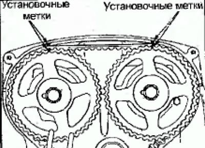
Fig. 2.42. Alignment of timing marks on camshaft pulleys with corresponding fixed marks
Warning: Turn the crankshaft clockwise only.
- Loosen the timing belt tensioner mechanism adjusting bolt and remove the belt.
Warning: If the timing belt is reused, use chalk to mark an arrow on the back (non-running) surface of the belt indicating the direction of rotation (clockwise).
- Remove the bolts and the automatic timing belt tensioner mechanism.
- Remove the bolt and pulley of the timing belt tensioner mechanism.
- Unscrew the bolt and remove the timing belt tensioner lever.
Examination
Toothed belt
After repairing the engine or adjusting the belt tension, check the condition of the belt. Replace the toothed belt if the following defects are present:
- hard back surface of the toothed belt or if the surface has a glossy appearance. The hardness of the surface is such that a fingernail does not leave marks on the belt (Fig. 2.43);
- cracks on the surface or delamination of the toothed belt (Fig. 2.44);
- cracks on the side surface of the toothed belt (Fig. 2.45) The side edges of the belt should have a pronounced right angle. If the side surface of the belt is twisted, then the belt is badly worn side surface;
- absence of a tooth, severely worn teeth or wear on the side of the tooth, exposing the fibers, cord and rubber base (Fig. 2.46).
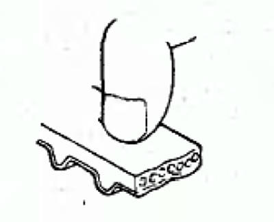
Fig.2.43. Checking the rigidity of the toothed belt surface
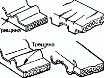
Fig. 2.44. Cracks on the surface or delamination of the toothed belt
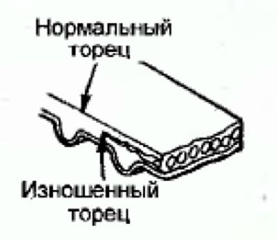
Fig. 2.45. Cracks or severe wear on the side surface of the toothed belt
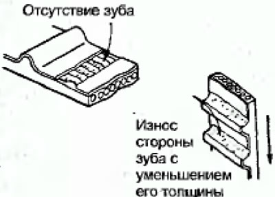
Fig.2.46. Severely worn teeth or wear on the tooth side of the timing belt
Automatic timing belt tensioning mechanism
Check the automatic timing belt tensioner mechanism for possible leaks (Fig. 2.47).
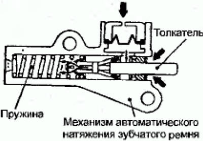
Fig. 2.47. Automatic toothed belt tensioning mechanism
Check the timing belt tensioner push rod for cracks and wear.
Check the serviceability of the automatic toothed belt tensioning mechanism by pressing the end of the pusher with a force of 98-196 N by hand and check the distance the pusher moves (Fig. 2.48). If the stroke of the tensioner pusher does not correspond to the required value, replace the toothed belt tensioning mechanism.
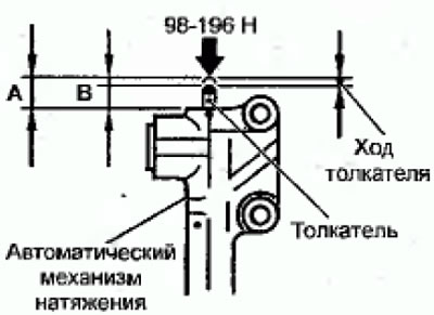
Fig. 2.48. Place of measuring the pusher stroke
Nominal distance value: about 1mm
A: the distance the plunger protrudes without applying force;
B: the distance the pusher protrudes when force is applied
A-B: pusher stroke = 1 mm
- If the value of the push rod movement does not correspond to the nominal value, replace the automatic timing belt tensioner mechanism
Installation
If the automatic timing belt tensioner pusher is fully extended from the housing, push it back as follows.
Warnings: When pressing the pusher into the automatic tensioning mechanism in a vice, position the pusher perpendicular to the vice jaws.
If the automatic tensioner has a plug at the base, install a flat washer on the end of the tensioner to protect it.
- Place two soft metal plates on the jaws of the vice. Then place the tensioning mechanism between the jaws of the vice.
Warning: Do not push the plunger out too quickly as it may be damaged.
- Slowly squeeze the jaws of the vice and press the pusher into the tensioner housing so that the holes in the pusher (A) and the housing (B, Fig. 2.49) are aligned.
- Insert a pin or steel wire with a diameter of 1.4 mm into the aligned holes and remove it
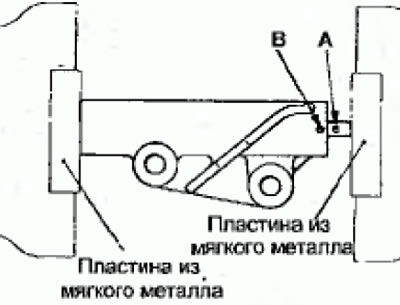
Fig. 2.49. Location of holes in the pusher (A) and housing (B) of the toothed belt tensioner mechanism
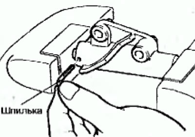
Fig. 2.50. Installing the stud into the aligned holes of the pusher and the housing of the toothed belt tensioner mechanism
Note: If a new timing belt tensioner is used, the pin will already be installed in the tensioner.
Warning: Do not remove the pin from the timing belt tensioner
- Install the timing belt tensioner onto the engine.
- Using special tools, turn the crankshaft into the pulley mounting bolt until the timing marks on the crankshaft pulley align with the corresponding fixed mark (Fig. 2.51).
- Align the timing marks on the camshaft pulleys with the corresponding fixed marks (see Fig. 2.51).
- Loosen the center bolt securing the tensioner pulley.
- Turn the crankshaft pulley counterclockwise half a tooth.
- Place the timing belt on the exhaust camshaft pulley and secure it with a double clamp (Fig. 2.52).
- Place the timing belt of the gas distribution mechanism drive on the camshaft pulley of the intake valves, while using two union keys to align the installation marks, as shown in Figure 2.53.
- Using a second double clamp, secure the timing belt to the intake camshaft pulley (Fig. 2.54).
- Install the toothed belt in sequence on the idler pulley, water pump pulley, crankshaft pulley and tensioner pulley (Fig. 2.55).
- Remove the clamps.
- Turn the tensioner pulley in the direction of the arrow shown in Figure 2.56 and tighten the tensioner pulley mounting bolt.
- Check that all alignment marks are aligned.
- Adjust the timing belt tension.
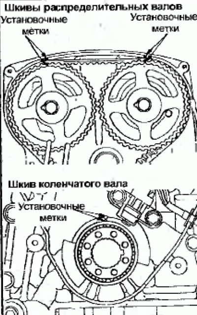
Fig. 2.51. Alignment of timing marks on the camshaft and crankshaft pulleys
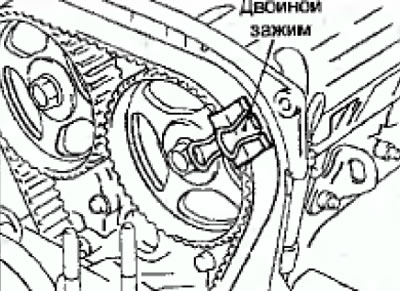
Fig. 2.52. Using a double clamp to secure the timing belt to the exhaust camshaft pulley
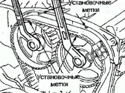
Fig. 2.53. Using two open-end wrenches to turn the camshafts and align the timing marks on the camshaft pulleys
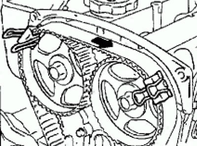
Fig. 2.54 Using a double clamp to secure the timing belt to the intake camshaft pulley
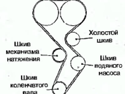
Fig. 2.55. Using two open-end wrenches to turn the camshafts and align the timing marks on the camshaft pulleys
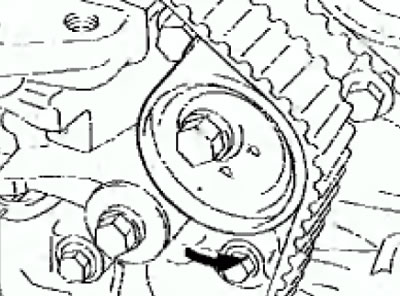
Fig. 2.56. Location of the toothed belt on the engine pulleys
Adjusting the timing belt tension
- Adjust the timing belt tension by turning the crankshaft ¼ turn counterclockwise and then returning it to its original position by turning it clockwise, making sure that all timing marks are aligned.
- Loosen the tensioner pulley fixing bolt and, using a special tool and a torque wrench, tighten the timing belt, then tighten the fixing bolt to a torque of 2.5-4.0 N·m (Fig. 2.57).
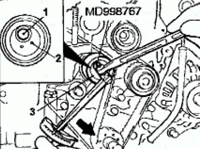
Fig. 2.57. Adjusting the tension of the timing belt: 1 - fixing bolt; 2 - pin hole; 3 - tension mechanism pulley
Caution: When tightening the locking bolt, make sure that the tensioner pulley does not move at this time.
- Remove the 2mm diameter dowel pin from the automatic tensioner (Fig. 2.58). Make sure the dowel pin can be removed easily.
- Turn the engine crankshaft 2 turns clockwise, wait for at least 5 minutes, then check that the 2mm diameter dowel pin can be easily pulled out or inserted into the hole of the automatic tensioner.
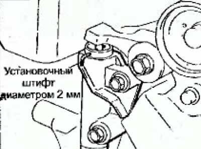
Fig.2.58 Removing a 2mm diameter dowel pin from the automatic tensioner
Note: Even if the dowel pin is not installed in the aligned holes, it will be sufficient if the rod protrudes from the tensioning mechanism within 3.8-4.5 mm (Fig. 2.59).
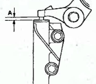
Fig. 2.59. Rod protrusion from the tensioning mechanism: A = 3.8 - 4.5 mm
Rod protrusion (A) from the tensioning mechanism: 3.8-4.5 mm
- If the protrusion value does not correspond to the nominal value, repeat the belt tensioning operations.
- Make sure the timing marks on all pulleys are aligned with the fixed marks.
- Install the flange.
- Install the lower protective cover.
- Install the engine mount bracket.
- Install the crankshaft pulley.
- Connect the cable to the negative terminal of the battery.