
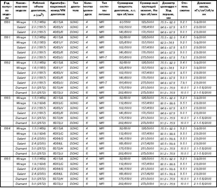
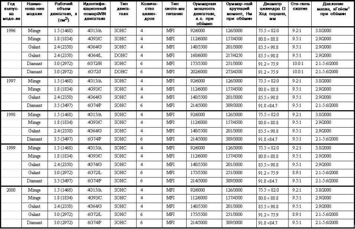
Where:
MFI = Distributed System (multipoint) injection
MFI-T = Turbocharged port injection system
SOHC = Single Overhead Camshaft Engines
DOHC = Double Overhead Camshaft Engines
Common parameters | |
Engine 1.5L | |
General Information | |
Engine type 4-cylinder in-line, SOHC | |
Working volume, l/cm3 | 1.5/1468 |
Cylinder diameter, mm | 75.49 |
Piston stroke, mm | 82 |
Compression ratio | 9.2:1 |
Ignition order | 1-3-4-2 |
Cylinder head | |
Full height, mm | 106.9÷107.1 |
Maximum allowable flatness of mating surfaces, mm | 0.05 |
Gap of landing of a camshaft in bearings, mm | 0.04÷0.08 |
Camshaft | |
Jaw height, mm | |
Intake valve cams | |
Rated value | 38.75 |
Minimum allowed value | 38.25 |
Exhaust cams | |
Rated value | 39.1 |
Minimum allowed value | 38.6 |
Diameter of bearing journals, mm | 46 |
Operating clearance in bearings, mm | |
Rated value | 0.06÷0.10 |
Limit value | 0.14 |
Rocker arms | |
Inner diameter, mm | 18.9 |
Landing clearance on axles, mm | |
Rated value | 0.01÷0.04 |
Limit value | 0.1 |
Rocker axles | |
Diameter, mm | 18.9 |
Length, mm | |
inlet | 100.75 |
graduation | 101.6 |
Rod diameter, mm | |
intake valves | 6.565÷6.580 |
exhaust valves | 6.530÷6.550 |
Bevel Angle | |
(inlet and outlet), deg | 45.0÷45.5 |
Width of the cylindrical part (girdle) plates, mm | |
Intake valves | |
Rated value | 1.0 |
Limit value | 0.5 |
Exhaust valves | |
Rated value | 1.5 |
Limit value | 1.0 |
Gap of landing rods in guide bushings, mm | |
Intake valves | |
Rated value | 0.02÷0.05 |
Limit value | 0.10 |
Exhaust valves | |
Rated value | 0.05÷0.09 |
Limit value | 0.15 |
Valve clearances, mm | |
Hot engine | |
intake valves | 0.15 |
exhaust valves | 0.25 |
Cold engine | |
intake valves | 0.07 |
exhaust valves | 0.17 |
Valve guides | |
Length, mm | |
Intake valve bushings | 44.0 |
Exhaust valve bushings | 49.5 |
Repair dimensions, mm | 0.05, 0.25, 0.50 |
Valve seats | |
Contact surface width | |
working chamfer, mm | 0.9÷1.3 mm |
Angle of inclination of the working chamfer, hail | 44.0÷44.5 |
Valve springs | |
Free length, mm | |
Inlet valve springs | |
Rated value | 46.1 |
Limit value | 45.1 |
Exhaust valve springs | |
Rated value | 46.8 |
Limit value | 45.8 |
Cylinder block | |
Total height, mm | |
Rated value | 255.9÷256.1 |
Limit value | 254.82 |
Maximum allowable out-of-flatness | |
gasket surface, mm | 0.1 |
Cylinder diameter, mm | 75.50÷75.53 |
Maximum allowable ovality of cylinders, mm | 0.02 |
Maximum allowable taper of cylinders, mm | 0.02 |
Pistons | |
Outer diameter, mm | 75.47÷75.50 |
Landing gap in cylinders, mm | 0.02÷0.04 |
Width of grooves for fitting piston rings, mm | |
First compression ring | 1.52÷1.54 |
Second compression ring | 1.51÷1.53 |
Oil scraper ring | 4.015÷4.045 |
Repair dimensions, mm | 0.05, 0.25, 0.50 |
Piston rings | |
Lateral clearance of fit in grooves, mm | |
First (upper) compression ring | |
Rated value | 0.03÷0.07 |
Limit value | 0.12 |
Second compression ring | |
Rated value | 0.02÷0.06 |
Limit value | 0.12 |
Clearances in locks, mm | |
First (upper) compression ring | |
Rated value | 0.20÷0.40 |
Limit value | 0.8 |
Second compression ring | |
Rated value | 0.20÷0.35 |
Limit value | 0.8 |
Oil wiper | |
Rated value | 0.20÷0.70 |
Limit value | 1.0 |
Maximum allowable bend, mm | 0.05 |
Maximum allowable twisting, mm | 0.10 |
Axial play of landing of the lower heads on the connecting rod journals of the crankshaft, mm | |
Rated value | 0.10÷0.25 |
Limit value | 0.4 |
Operating clearance in connecting rod bearings, mm | |
Rated value | 0.02÷0.06 |
Limit value | 0.15 |
Crankshaft | |
Working clearance in main bearings, mm | |
Rated value | 0.02÷0.07 |
Limit value | 0.15 |
Diameter of connecting rod journals, mm | 42 |
Diameter of main journals, mm | 48 |
Maximum allowable neck ovality, mm | 0.015 |
Shaft end play, mm | |
Rated value | 0.05÷0.18 |
Limit value | 0.25 |
Flywheel | |
Limit value of runout, mm | 0.13 |
Oil pump | |
Gap on gear teeth, mm | |
Rated value | 0.06÷0.18 |
Limit value | 0.35 |
Side clearance, mm | |
Rated value | 0.04÷0.10 |
Limit value | 0.20 |
Landing gap in the body, mm | |
Rated value | 0.10÷0.18 |
Limit value | 0.35 |
Free length of pressure reducing valve spring, mm | 46.6 |
Under load 61 Nm, mm | 40.1 |
Engine 1.6 l | |
General Information | |
engine's type | 4-cylinder in-line, DOHC |
Working volume, l/cm3 | 1.6/1565 |
Cylinder diameter, mm | 82.3 |
Piston stroke, mm | 75 |
Compression ratio | 9.2:1 |
Ignition order | 1-3-4-2 |
Cylinder head | |
Full height, mm | 131.9÷132.1 |
Maximum allowable flatness of mating surfaces, mm | 0.05 |
Gap of landing of a camshaft in bearings, mm | 0.04÷0.08 |
Camshaft | |
Jaw height, mm | |
Intake valve cams | |
Rated value | 35.20 |
Minimum allowed value | 34.70 |
Exhaust cams | |
Rated value | 34.907 |
Minimum allowed value | 34.407 |
Diameter of bearing journals, mm | 26 |
Operating clearance in bearings, mm | 0.05÷0.09 |
Axial play, mm | 0.1÷0.2 |
Length, mm | |
inlet | 109.50 |
graduation | 109.70 |
Rod diameter, mm | |
intake valves | 6.565÷6.568 |
exhaust valves | 6.530÷6.550 |
Bevel Angle | |
(inlet and outlet), deg | 45.0÷45.5 |
Width of the cylindrical part (girdle) plates, mm | |
Intake valves | |
Rated value | 1.0 |
Limit value | 0.7 |
Exhaust valves | |
Rated value | 1.5 |
Limit value | 1.0 |
Gap of landing rods in guide bushings, mm | |
Intake valves | |
Rated value | 0.02÷0.05 |
Limit value | 0.10 |
Exhaust valves | |
Rated value | 0.05÷0.09 |
Limit value | 0.15 |
Valve guides | |
Length, mm | |
Intake valve bushings | 45.5 |
Exhaust valve bushings | 50.5 |
Repair dimensions, mm | 0.05, 0.25, 0.50 |
Valve seats | |
Width of the contact surface of the working chamfer, mm | 0.9÷1.3 mm |
Angle of inclination of the working chamfer, hail | 44.0÷44.5 |
valve springs | |
Free length, mm | |
Rated value | 48.3 |
Limit value | 47.3 |
Misalignment, hail | |
Rated value | Less than 1.5 |
Limit value | 4.0 |
Cylinder block | |
Maximum permissible non-flatness of the gasket surface, mm | 0.1 |
Cylinder diameter, mm | 82.30÷82.33 |
Maximum allowable ovality of cylinders, mm | 0.01 |
Maximum allowable taper of cylinders, mm | 0.01 |
Pistons | |
Outer diameter, mm | 82.27÷82.30 |
Landing gap in cylinders, mm | 0.02÷0.04 |
Groove width for piston rings, mm | |
First compression ring | 1.22÷1.24 |
Second compression ring | 1.52÷1.54 |
Oil scraper ring | 3.01÷3.03 |
Repair dimensions, mm | 0.25, 0.50, 0.75, 1.0 |
Piston rings | |
Lateral clearance of landing in grooves, mm | |
First (upper) compression ring | |
Rated value | 0.03÷0.07 |
Limit value | 0.12 |
Second compression ring | |
Rated value | 0.03÷0.07 |
Limit value | 0.12 |
Gaps in locks, mm | |
First (upper) compression ring | |
Rated value | 0.25÷0.40 |
Limit value | 0.8 |
Second compression ring | |
Rated value | 0.35÷0.50 |
Limit value | 1.0 |
Oil scraper ring | |
Rated value | 0.20÷0.70 |
Limit value | 1.0 |
Repair dimensions, mm | 0.25, 0.50, 0.75, 1.0 |
connecting rods | |
Maximum allowable bend, mm | 0.05 |
Maximum allowable twisting, mm | 0.10 |
Axial play of landing of the lower heads on the connecting rod journals of the crankshaft, mm | |
Rated value | 0.10÷0.25 |
Limit value | 0.4 |
Operating clearance in connecting rod bearings, mm | |
Rated value | 0.02÷0.05 |
Limit value | 0.1 |
Crankshaft | |
Working clearance in main bearings, mm | |
Rated value | 0.02÷0.05 |
Limit value | 0.1 |
Diameter of connecting rod journals, mm | 45 |
Diameter of main journals, mm | 57 |
Maximum allowable neck ovality, mm | 0.015 |
Shaft end play, mm | |
Rated value | 0.05÷0.18 |
Limit value | 0.25 |
Flywheel | |
Limit value of runout, mm | 0.13 |
Oil pump | |
Gap on gear teeth, mm | |
pinion gear | |
Rated value | 0.16÷0.21 |
Limit value | 0.25 |
driven gear | |
Rated value | 0.13÷0.18 |
Limit value | 0.25 |
Side clearance, mm | |
pinion gear | |
Rated value | 0.08÷0.14 |
Limit value | 0.25 |
driven gear | |
Rated value | 0.06÷0.12 |
Limit value | 0.25 |
Free length of pressure reducing valve spring, mm | 46.6 |
Engine 1.8 l | |
general information | |
engine's type | 4-cylinder in-line, SOHC |
Working volume, l/cm3 | 1.8/1834 |
Cylinder diameter, mm | 81 |
Piston stroke, mm | 89 |
Compression ratio | 9.5:1 |
Ignition order | 1-3-4-2 |
cylinder head | |
Full height, mm | 119.9÷120.1 |
Maximum allowable | |
flatness of mating surfaces, mm | 0.2 |
Camshaft | |
Jaw height, mm | |
Intake valve cams | |
Rated value | 37.11 |
Minimum allowed value | 36.61 |
Exhaust valve cams | |
Rated value | 37.15 |
Minimum allowed value | 36.65 |
valves | |
Length, mm | |
inlet | |
Rated value | 110.15 |
Limit value | 109.65 |
graduation | |
Rated value | 113.70 |
Limit value | 113.25 |
Rod diameter, mm | |
intake valves | 6.0 |
exhaust valves | 6.0 |
Angle of inclination of the working chamfer | |
(inlet and outlet), deg | 45.0÷45.5 |
Width of the cylindrical part (girdle) plates, mm | |
intake valves | |
Rated value | 1.0 |
Limit value | 0.5 |
exhaust valves | |
Rated value | 1.3 |
Limit value | 0.8 |
Gap of landing rods in guide bushings, mm | |
intake valves | |
Rated value | 0.02÷0.05 |
Limit value | 0.10 |
exhaust valves | |
Rated value | 0.05÷0.09 |
Limit value | 0.15 |
Valve guides | |
Elevation, mm | 14.0 |
Inner diameter, mm | 6.0 |
valve seats | |
Width of the contact surface of the working chamfer, mm | 0.9÷1.3 mm |
Angle of inclination of the working chamfer, hail | 44.0÷44.5 |
valve springs | |
Free length, mm | |
Inlet valve springs | |
Rated value | 50.9 |
Limit value | 49.9 |
Exhaust valve springs | |
Rated value | 50.9 |
Limit value | 49.9 |
Cylinder block | |
Full height, mm | 263.5 |
Maximum permissible non-flatness of the gasket surface, mm | 0.1 |
Cylinder diameter, mm | 81.0 |
Maximum allowable ovality of cylinders, mm | 0.01 |
Maximum allowable taper of cylinders, mm | 0.01 |
Pistons | |
Outer diameter, mm | 81.0 |
Piston pin diameter, mm | 19.0 |
Landing gap in cylinders, mm | 0.02÷0.04 |
Piston rings | |
Lateral clearance of landing in grooves, mm | |
First (upper) compression ring | |
Rated value | 0.03÷0.07 |
Limit value | 0.1 |
Second compression ring | |
Rated value | 0.02÷0.06 |
Limit value | 0.1 |
Gaps in locks, mm | |
First (upper) compression ring | |
Rated value | 0.25÷0.40 |
Limit value | 0.8 |
Second compression ring | |
Rated value | 0.40÷0.55 |
Limit value | 0.8 |
Oil scraper ring | |
Rated value | 0.20÷0.60 |
Limit value | 1.0 |
connecting rods | |
Axial play of landing of the lower heads on the connecting rod journals of the crankshaft, mm | |
Rated value | 0.10÷0.25 |
Limit value | 0.4 |
Operating clearance in connecting rod bearings, mm | |
Rated value | 0.02÷0.08 |
Limit value | 0.1 |
Crankshaft | |
Diameter of main journals, mm | 50 |
Diameter of connecting rod journals, mm | 45 |
Working clearance in main bearings, mm | |
Rated value | 0.02÷0.04 |
Limit value | 0.1 |
Maximum allowable neck ovality, mm | 0.015 |
Shaft end play, mm | |
Rated value | 0.05÷0.25 |
Limit value | 0.1 |
Oil pump | |
Gap on gear teeth, mm | |
Rated value | 0.06÷0.18 |
Limit value | 0.35 |
Side clearance, mm | |
Rated value | 0.04÷0.10 |
Limit value | 0.20 |
Landing clearance in the body, mm | |
Rated value | 0.10÷0.18 |
Limit value | 0.35 |
Engine 2.0 l SOHC | |
general information | |
Engine type 4-cylinder in-line, SOHC | |
Working volume, l/cm3 | 2.0/1997 |
Cylinder diameter, mm | 85 |
Piston stroke, mm | 88 |
Compression ratio | 8.5:1 |
Ignition order | 1-3-4-2 |
cylinder head | |
Full height, mm | 89.9÷90.1 |
Maximum allowable flatness of mating surfaces, mm | 0.2 |
Camshaft | |
Jaw height, mm | |
Cams marked D | |
intake valve drive | |
Rated value | 42.4 |
Minimum allowed value | 41.9 |
Exhaust valve drive | |
Rated value | 42.4 |
Minimum allowed value | 41.9 |
Cams with AR marking | |
Exhaust valve drive | |
Rated value | 44.53 |
Minimum allowed value | 44.03 |
Exhaust valve drive | |
Rated value | 44.53 |
Minimum allowed value | 44.03 |
Diameter of bearing journals, mm | 33.95 |
valves | |
Rod diameter, mm | |
intake valves | 8.0 |
exhaust valves | 7.9 |
Angle of inclination of the working chamfer | |
(inlet and outlet), deg | 45.0÷45.5 |
Width of the cylindrical part (girdle) plates, mm | |
intake valves | |
Rated value | 1.2 |
Limit value | 0.5 |
exhaust valves | |
Rated value | 2.0 |
Limit value | 0.8 |
Gap of landing rods in guide bushings, mm | |
intake valves | |
Rated value | 0.03÷0.06 |
Limit value | 0.10 |
exhaust valves | |
Rated value | 0.05÷0.09 |
Limit value | 0.15 |
Valve guides | |
Inner diameter, mm | 8.0 |
Outer diameter, mm | 13.1 |
valve seats | |
Contact surface width | |
working chamfer, mm | 0.9÷1.3 mm |
Angle of inclination of the working chamfer, hail | 44.0÷44.5 |
valve springs | |
Free length, mm | |
Rated value | 49.8 |
Limit value | 49.9 |
Misalignment, hail | |
Rated value | 2 |
Limit value | 4 |
Cylinder block | |
Full height, mm | 289.9÷290.1 |
Maximum allowable non-flatness | |
gasket surface, mm | 0.05 |
Cylinder diameter, mm | 85 |
Maximum allowable ovality of cylinders, mm | 0.02 |
Maximum allowable taper of cylinders, mm | 0.02 |
Pistons | |
Outer diameter, mm | 84.99 |
Landing gap in cylinders, mm | 0.01÷0.03 |
Piston rings | |
Lateral clearance of landing in grooves, mm | |
First (upper) compression ring | |
Rated value | 0.03÷0.07 |
Limit value | 0.1 |
Second compression ring | |
Rated value | 0.02÷0.06 |
Limit value | 0.1 |
Gaps in locks, mm | |
First (upper) compression ring | |
Rated value | 0.25÷0.40 |
Limit value | 0.8 |
Second compression ring | |
Rated value | 0.20÷0.35 |
Limit value | 0.8 |
Oil scraper ring | |
Rated value | 0.20÷0.70 |
Limit value | 1.0 |
connecting rods | |
Axial play of landing of the lower heads on the connecting rod journals of the crankshaft, mm | |
Rated value | 0.10÷0.25 |
Limit value | 0.4 |
Piston pin diameter, mm | 21 |
Operating clearance in connecting rod bearings, mm | |
Rated value | 0.02÷0.05 |
Limit value | 0.1 |
Crankshaft | |
Working clearance in main bearings, mm | |
Rated value | 0.02÷0.05 |
Limit value | 0.1 |
Diameter of connecting rod journals, mm | 45 |
Diameter of main journals, mm | 57 |
Maximum allowable neck ovality, mm | 0.015 |
Shaft end play, mm | |
Rated value | 0.05÷0.18 |
Limit value | 0.25 |
Flywheel | |
Limit value of runout, mm | 0.13 |
Oil pump | |
Side clearance, mm | |
pinion gear | 0.08÷0.14 |
driven gear | 0.06÷0.12 |
Naturally aspirated 2.0L DOHC engine | |
general information | |
Engine type 4-cylinder in-line, DOHC | |
Working volume, l/cm3 | 2.0/1997 |
Cylinder diameter, mm | 85 |
Piston stroke, mm | 88 |
Compression ratio | 9.8:1 |
Ignition order | 1-3-4-2 |
cylinder head | |
Full height, mm | 131.9÷132.1 |
Maximum allowable | |
flatness of mating surfaces, mm | 0.2 |
Camshafts | |
Jaw height, mm | |
Cams marked A, D | |
intake valve drive | |
Rated value | 35.49 |
Minimum allowed value | 34.99 |
Cams marked B, C, E, F | |
intake valve drive | |
Rated value | 35.20 |
Minimum allowed value | 34.70 |
Cams marked A | |
Exhaust valve drive | |
Rated value | 35.20 |
Minimum allowed value | 34.70 |
C-marked cams | |
Exhaust valve drive | |
Rated value | 35.49 |
Minimum allowed value | 34.99 |
Cams marked E, F | |
Exhaust valve drive | |
Rated value | 34.91 |
Minimum allowed value | 34.41 |
Diameter of bearing journals, mm | 25.96 |
valves | |
Rod diameter, mm | |
intake valves | 6.6 |
exhaust valves | 6.5 |
Angle of inclination of the working chamfer (inlet and outlet), deg | 45.0÷45.5 |
Width of the cylindrical part (girdle) plates, mm | |
intake valves | |
Rated value | 1.0 |
Limit value | 0.5 |
exhaust valves | |
Rated value | 1.5 |
Limit value | 0.8 |
Gap of landing rods in guide bushings, mm | |
intake valves | |
Rated value | 0.02÷0.05 |
Limit value | 0.10 |
exhaust valves | |
Rated value | 0.05÷0.09 |
Limit value | 0.15 |
Valve guides | |
Inner diameter, mm | 6.6 |
Outer diameter, mm | 12.1 |
valve seats | |
Contact surface width | |
working chamfer, mm | 0.9÷1.3 mm |
Angle of inclination of the working chamfer, hail | 44.0÷44.5 |
valve springs | |
Free length, mm | |
Rated value | 48.3 |
Limit value | 49.9 |
Misalignment, hail | |
Rated value | 2 |
Limit value | 4 |
Cylinder block | |
Full height, mm | 289.9÷290.1 |
Maximum permissible non-flatness of the gasket surface, mm | 0.05 |
Cylinder diameter, mm | 85 |
Maximum allowable ovality of cylinders, mm | 0.02 |
Maximum allowable taper of cylinders, mm | 0.02 |
Pistons | |
Outer diameter, mm | 84.99 |
Landing gap in cylinders, mm | 0.02÷0.04 |
Piston rings | |
Lateral clearance of landing in grooves, mm | |
First (upper) compression ring | |
Rated value | 0.03÷0.07 |
Limit value | 0.1 |
Second compression ring | |
Rated value | 0.03÷0.07 |
Limit value | 0.1 |
Gaps in locks, mm | |
First (upper) compression ring | |
Rated value | 0.25÷0.40 |
Limit value | 0.8 |
Second compression ring | |
Rated value | 0.45÷0.60 |
Limit value | 0.8 |
Oil scraper ring | |
Rated value | 0.20÷0.70 |
Limit value | 1.0 |
connecting rods | |
Axial play of landing of the lower heads on the connecting rod journals of the crankshaft, mm | |
Rated value | 0.10÷0.25 |
Limit value | 0.4 |
Piston pin diameter, mm | 21 |
Operating clearance in connecting rod bearings, mm | |
Rated value | 0.02÷0.05 |
Limit value | 0.1 |
Crankshaft | |
Working clearance in main bearings, mm | |
Rated value | 0.02÷0.05 |
Limit value | 0.1 |
Diameter of connecting rod journals, mm | 45 |
Diameter of main journals, mm | 57 |
Maximum allowable neck ovality, mm | 0.015 |
Shaft end play, mm | |
Rated value | 0.05÷0.18 |
Limit value | 0.25 |
Flywheel | |
Limit value of runout, mm | 0.13 |
Oil pump | |
Side clearance, mm | |
pinion gear | 0.08÷0.14 |
driven gear | 0.06÷0.12 |
Turbocharged 2.0L DOHC engine | |
general information | |
Engine type 4-cylinder in-line, DOHC | |
Working volume, l/cm3 | 2.0/1997 |
Cylinder diameter, mm | 85 |
Piston stroke, mm | 88 |
Compression ratio | 7.8:1 |
Ignition order | 1-3-4-2 |
cylinder head | |
Full height, mm | 131.9÷132.1 |
Maximum allowable flatness of mating surfaces, mm | 0.2 |
Camshafts | |
Jaw height, mm | |
Cams marked A, D | |
intake valve drive | |
Rated value | 35.49 |
Minimum allowed value | 34.99 |
Cams marked B, C, E, F | |
intake valve drive | |
Rated value | 35.20 |
Minimum allowed value | 34.70 |
Cams marked A | |
Exhaust valve drive | |
Rated value | 35.20 |
Minimum allowed value | 34.70 |
C-marked cams | |
Exhaust valve drive | |
Rated value | 35.49 |
Minimum allowed value | 34.99 |
Cams marked E, F | |
Exhaust valve drive | |
Rated value | 34.91 |
Minimum allowed value | 34.41 |
Diameter of bearing journals, mm | 25.96 |
valves | |
Rod diameter, mm | |
intake valves | 6.6 |
exhaust valves | 6.5 |
Angle of inclination of the working chamfer (inlet and outlet), deg | 45.0÷45.5 |
Width of the cylindrical part (girdle) plates, mm | |
intake valves | |
Rated value | 1.0 |
Limit value | 0.5 |
exhaust valves | |
Rated value | 1.5 |
Limit value | 0.8 |
Gap of landing rods in guide bushings, mm | |
intake valves | |
Rated value | 0.02÷0.05 |
Limit value | 0.10 |
exhaust valves | |
Rated value | 0.05÷0.09 |
Limit value | 0.15 |
Valve guides | |
Inner diameter, mm | 6.6 |
Outer diameter, mm | 12.1 |
valve seats | |
Width of the contact surface of the working chamfer, mm | 0.9÷1.3 mm |
Angle of inclination of the working chamfer, hail | 44.0÷44.5 |
valve springs | |
Free length, mm | |
Rated value | 48.3 |
Limit value | 49.9 |
Misalignment, hail | |
Rated value | 2 |
Limit value | 4 |
Cylinder block | |
Full height, mm | 289.9÷290.1 |
Maximum permissible non-flatness of the gasket surface, mm | 0.05 |
Cylinder diameter, mm | 85 |
Maximum allowable ovality of cylinders, mm | 0.02 |
Maximum allowable taper of cylinders, mm | 0.02 |
Pistons | |
Outer diameter, mm | 84.98 |
Landing gap in cylinders, mm | 0.03÷0.05 |
Piston rings | |
Lateral clearance of landing in grooves, mm | |
First (upper) compression ring | |
Rated value | 0.03÷0.07 |
Limit value | 0.1 |
Second compression ring | |
Rated value | 0.03÷0.07 |
Limit value | 0.1 |
Gaps in locks, mm | |
First (upper) compression ring | |
Rated value | 0.25÷0.40 |
Limit value | 0.8 |
Second compression ring | |
Rated value | 0.45÷0.60 |
Limit value | 0.8 |
Oil scraper ring | |
Rated value | 0.20÷0.70 |
Limit value | 1.0 |
connecting rods | |
Axial play of landing of the lower heads on the connecting rod journals of the crankshaft, mm | |
Rated value | 0.10÷0.25 |
Limit value | 0.4 |
Piston pin diameter, mm | 21 |
Operating clearance in connecting rod bearings, mm | |
Rated value | 0.02÷0.05 |
Limit value | 0.1 |
Crankshaft | |
Working clearance in main bearings, mm | |
Rated value | 0.02÷0.05 |
Limit value | 0.1 |
Diameter of connecting rod journals, mm | 45 |
Diameter of main journals, mm | 57 |
Maximum allowable neck ovality, mm | 0.015 |
Shaft end play, mm | |
Rated value | 0.05÷0.18 |
Limit value | 0.25 |
Flywheel | |
Limit value of runout, mm | 0.13 |
Oil pump | |
Side clearance, mm | |
pinion gear | 0.08÷0.14 |
driven gear | 0.06÷0.12 |
Engine 2.4 l SOHC | |
general information | |
engine's type | 4-cylinder in-line, SOHC |
Working volume, l/cm3 | 2.4/2350 |
Cylinder diameter, mm | 86.5 |
Piston stroke, mm | 100 |
Compression ratio | 8.5:1 |
Ignition order | 1-3-4-2 |
cylinder head | |
Full height, mm | 89.9÷90.1 |
Maximum allowable flatness of mating surfaces, mm | 0.2 |
Camshaft | |
Jaw height, mm | |
Cams marked D | |
intake valve drive | |
Rated value | 42.4 |
Minimum allowed value | 41.9 |
Exhaust valve drive | |
Rated value | 42.4 |
Minimum allowed value | 41.9 |
Cams with AR marking | |
intake valve drive | |
Rated value | 44.53 |
Minimum allowed value | 44.03 |
Exhaust valve drive | |
Rated value | 44.53 |
Minimum allowed value | 44.03 |
Diameter of bearing journals, mm | 33.95 |
valves | |
Rod diameter, mm | |
intake valves | 8.0 |
exhaust valves | 7.9 |
Angle of inclination of the working chamfer (inlet and outlet), deg | 45.0÷45.5 |
Width of the cylindrical part (girdle) plates, mm | |
intake valves | |
Rated value | 1.2 |
Limit value | 0.5 |
exhaust valves | |
Rated value | 2.0 |
Limit value | 0.8 |
Gap of landing rods in guide bushings, mm | |
intake valves | |
Rated value | 0.03÷0.06 |
Limit value | 0.10 |
exhaust valves | |
Rated value | 0.05÷0.09 |
Limit value | 0.15 |
Valve guides | |
Inner diameter, mm | 8.0 |
Outer diameter, mm | 13.1 |
valve seats | |
Width of the contact surface of the working chamfer, mm | 0.9÷1.3 mm |
Angle of inclination of the working chamfer, hail | 44.0÷44.5 |
valve springs | |
Free length, mm | |
Rated value | 49.8 |
Limit value | 49.9 |
Misalignment, hail | |
Rated value | 2 |
Limit value | 4 |
Cylinder block | |
Full height, mm | 289.9÷290.1 |
Maximum permissible non-flatness of the gasket surface, mm | 0.05 |
Cylinder diameter, mm | 85 |
Maximum allowable ovality of cylinders, mm | 0.02 |
Maximum allowable taper of cylinders, mm | 0.02 |
Pistons | |
Outer diameter, mm | 84.99 |
Landing gap in cylinders, mm | 0.01÷0.03 |
Piston rings | |
Lateral clearance of landing in grooves, mm | |
First (upper) compression ring | |
Rated value | 0.03÷0.07 |
Limit value | 0.1 |
Second compression ring | |
Rated value | 0.02÷0.06 |
Limit value | 0.1 |
Gaps in locks, mm | |
First (upper) compression ring | |
Rated value | 0.25÷0.40 |
Limit value | 0.8 |
Second compression ring | |
Rated value | 0.20÷0.35 |
Limit value | 0.8 |
Oil scraper ring | |
Rated value | 0.20÷0.70 |
Limit value | 1.0 |
connecting rods | |
Axial play of landing of the lower heads on the connecting rod journals of the crankshaft, mm | |
Rated value | 0.10÷0.25 |
Limit value | 0.4 |
Piston pin diameter, mm | 21 |
Operating clearance in connecting rod bearings, mm | |
Rated value | 0.02÷0.05 |
Limit value | 0.1 |
Crankshaft | |
Working clearance in main bearings, mm | |
Rated value | 0.02÷0.05 |
Limit value | 0.1 |
Diameter of connecting rod journals, mm | 45 |
Diameter of main journals, mm | 57 |
Maximum allowable neck ovality, mm | 0.015 |
Shaft end play, mm | |
Rated value | 0.05÷0.18 |
Limit value | 0.25 |
Flywheel | |
Limit value of runout, mm | 0.13 |
Oil pump | |
Side clearance, mm | |
pinion gear | 0.08÷0.14 |
driven gear | 0.06÷0.12 |
Engine 2.4 l DOHC | |
general information | |
engine's type | 4-cylinder in-line, DOHC |
Working volume, l/cm3 | 2.4/2350 |
Cylinder diameter, mm | 86.5 |
Piston stroke, mm | 100 |
Compression ratio | 8.5:1 |
Ignition order | 1-3-4-2 |
cylinder head | |
Full height, mm | 131.9÷132.1 |
Maximum allowable flatness of mating surfaces, mm | 0.2 |
Camshafts | |
Jaw height, mm | |
Cams marked A, D | |
intake valve drive | |
Rated value | 35.49 |
Minimum allowed value | 34.99 |
Cams marked B, C, E, F | |
intake valve drive | |
Rated value | 35.20 |
Minimum allowed value | 34.70 |
Cams marked A | |
Exhaust valve drive | |
Rated value | 35.20 |
Minimum allowed value | 34.70 |
C-marked cams | |
Exhaust valve drive | |
Rated value | 35.49 |
Minimum allowed value | 34.99 |
Cams marked E, F | |
Exhaust valve drive | |
Rated value | 34.91 |
Minimum allowed value | 34.41 |
Diameter of bearing journals, mm | 25.96 |
valves | |
Rod diameter, mm | |
intake valves | 6.6 |
exhaust valves | 6.5 |
Angle of inclination of the working chamfer (inlet and outlet), deg | 45.0÷45.5 |
Width of the cylindrical part (girdle) plates, mm | |
intake valves | |
Rated value | 1.0 |
Limit value | 0.5 |
exhaust valves | |
Rated value | 1.5 |
Limit value | 0.8 |
Gap of landing rods in guide bushings, mm | |
intake valves | |
Rated value | 0.02÷0.05 |
Limit value | 0.10 |
exhaust valves | |
Rated value | 0.05÷0.09 |
Limit value | 0.15 |
Valve guides | |
Inner diameter, mm | 6.6 |
Outer diameter, mm | 12.1 |
valve seats | |
Contact surface width | |
working chamfer, mm | 0.9÷1.3 mm |
The angle of inclination of the working chamfer, degrees 4 | 4.0÷44.5 |
valve springs | |
Free length, mm | |
Rated value | 48.3 |
Limit value | 49.9 |
Misalignment, hail | |
Rated value | 2 |
Limit value | 4 |
Cylinder block | |
Full height, mm | 289.9÷290.1 |
Maximum permissible non-flatness of the gasket surface, mm | 0.05 |
Cylinder diameter, mm | 85 |
Maximum allowable ovality of cylinders, mm | 0.02 |
Maximum allowable taper of cylinders, mm | 0.02 |
Pistons | |
Outer diameter, mm | 84.99 |
Landing gap in cylinders, mm | 0.02÷0.04 |
Piston rings | |
Lateral clearance of landing in grooves, mm | |
First (upper) compression ring | |
Rated value | 0.03÷0.07 |
Limit value | 0.1 |
Second compression ring | |
Rated value | 0.03÷0.07 |
Limit value | 0.1 |
Gaps in locks, mm | |
First (upper) compression ring | |
Rated value | 0.25÷0.40 |
Limit value | 0.8 |
Second compression ring | |
Rated value | 0.45÷0.60 |
Limit value | 0.8 |
Oil scraper ring | |
Rated value | 0.20÷0.70 |
Limit value | 1.0 |
connecting rods | |
Axial play of landing of the lower heads on the connecting rod journals of the crankshaft, mm | |
Rated value | 0.10÷0.25 |
Limit value | 0.4 |
Piston pin diameter, mm | 21 |
Operating clearance in connecting rod bearings, mm | |
Rated value | 0.02÷0.05 |
Limit value | 0.1 |
Crankshaft | |
Working clearance in main bearings, mm | |
Rated value | 0.02÷0.05 |
Limit value | 0.1 |
Diameter of connecting rod journals, mm | 45 |
Diameter of main journals, mm | 57 |
Maximum allowable neck ovality, mm | 0.015 |
Shaft end play, mm | |
Rated value | 0.05÷0.18 |
Limit value | 0.25 |
Flywheel | |
Limit value of runout, mm | 0.13 |
Oil pump | |
Side clearance, mm | |
pinion gear | 0.08÷0.14 |
driven gear | 0.06÷0.12 |
Engine 3.0 l SOHC | |
General Information | |
engine's type | 6-cylinder V-shaped (60°), SOHC |
Working volume, l/cm3 | 3.0/2972 |
Cylinder diameter, mm | 91.1 |
Piston stroke, mm | 76 |
Compression ratio | 10.0:1 |
Ignition order | 1-2-3-4-5-6 |
cylinder head | |
Full height, mm | 84 |
Maximum allowable flatness of mating surfaces, mm | 0.2 |
Camshaft | |
Jaw height, mm | |
Rated value | 41.25 |
Minimum allowed value | 40.75 |
Diameter of bearing journals, mm | 33.95 |
valves | |
Rod diameter, mm | |
intake valves | 8.0 |
exhaust valves | 7.9 |
Angle of inclination of the working chamfer (inlet and outlet), deg | 45.0÷45.5 |
Width of the cylindrical part (girdle) plates, mm | |
intake valves | |
Rated value | 1.2 |
Limit value | 0.7 |
exhaust valves | |
Rated value | 2.0 |
Limit value | 1.5 |
Gap of landing rods in guide bushings, mm | |
intake valves | |
Rated value | 0.03÷0.06 |
Limit value | 0.10 |
exhaust valves | |
Rated value | 0.05÷0.09 |
Limit value | 0.15 |
Valve guides | |
Inner diameter, mm | 8.0 |
Outer diameter, mm | 13.1 |
valve seats | |
Width of the contact surface of the working chamfer, mm | 0.9÷1.3 mm |
Angle of inclination of the working chamfer, hail | 44.0÷44.5 |
valve springs | |
Free length, mm | |
Rated value | 49.8 |
Limit value | 48.8 |
Misalignment, hail | |
Rated value | 2 |
Limit value | 4 |
Cylinder block | |
Full height, mm | 210.4÷210.6 |
Maximum permissible non-flatness of the gasket surface, mm | 0.1 |
Cylinder diameter, mm | 91.1 |
Maximum allowable ovality of cylinders, mm | 0.02 |
Maximum allowable taper of cylinders, mm | 0.02 |
Pistons | |
Outer diameter, mm | 91.1 |
Landing gap in cylinders, mm | 0.02÷0.04 |
Piston rings | |
Lateral clearance of landing in grooves, mm | |
First (upper) compression ring | |
Rated value | 0.03÷0.07 |
Limit value | 0.1 |
Second compression ring | |
Rated value | 0.02÷0.06 |
Limit value | 0.1 |
Gaps in locks, mm | |
First (upper) compression ring | |
Rated value | 0.30÷0.40 |
Limit value | 0.8 |
Second compression ring | |
Rated value | 0.45÷0.60 |
Limit value | 0.8 |
Oil scraper ring | |
Rated value | 0.20÷0.60 |
Limit value | 1.0 |
connecting rods | |
Axial play of landing of the lower heads on the connecting rod journals of the crankshaft, mm | |
Rated value | 0.10÷0.25 |
Limit value | 0.4 |
Piston pin diameter, mm | 22 |
Operating clearance in connecting rod bearings, mm | |
Rated value | 0.02÷0.05 |
Limit value | 0.1 |
Crankshaft | |
Working clearance in main bearings, mm | |
Rated value | 0.02÷0.05 |
Limit value | 0.1 |
Diameter of connecting rod journals, mm | 50 |
Diameter of main journals, mm | 60 |
Maximum allowable neck ovality, mm | 0.015 |
Shaft end play, mm | |
Rated value | 0.05÷0.25 |
Limit value | 0.3 |
Oil pump | |
Gap on gear teeth, mm | 0.06÷0.18 |
Side clearance, mm | 0.04÷0.10 |
Landing gap in the body, mm | |
Rated value | 0.10÷0.18 |
Limit value | 0.35 |
Tightening torque of threaded connections, Nm* | |
Camshaft | |
Gear Bolt | |
Engines 1.5 l | 70 |
Engines 1.6 l, 1.8 l and 2.0 l (SOHC and DOHC) | 90 |
Engines 2.4 l | 80÷100 |
Engines 3.0 l (SOHC and DOHC) | 90 |
Bearing cap bolts | |
2.0L SOHC engines | 20 |
Engines 1.6 l and 2.0 DOHC | 29÷35 |
Engines 2.4 l | 20 |
Engines 3.0 l (SOHC and DOHC) | 90 |
Engines 3.5 l | 31 |
Crankshaft pulley/vibration damper | |
Pulley bolts | |
Engines 1.5 l | 14 |
Engines 1.6 l and 2.0 l (SOHC and DOHC) | 20÷30 |
Engines 2.4 l | 25 |
Center fixing bolt | |
Engines 1.5 l | 70÷100 |
Engines 1.8 l and 3.5 l | 185 |
Engines 3.0 l (SOHC and DOHC) | 150÷160 |
Cylinder head | |
Head bolts | |
1.5L | |
Stage 1 | 49 |
Stage 2 | Loosen all bolts completely (in reverse order of tightening - see Section Removal and installation of a head of cylinders) |
Stage 3 | 20 |
Stage 4 | Pull another 90° |
Stage 5 | Pull another 90° |
1.8L | |
Stage 1 | 75 |
Stage 2 | Loosen all bolts completely (in reverse order of tightening - see Section Removal and installation of a head of cylinders) |
Stage 3 | 20 |
Stage 4 | Pull another 90° |
Stage 5 | Pull another 90° |
2.0L SOHC | |
Stage 1 | 30 |
Stage 2 | 61 |
Stage 3 | 92 |
1.6L and 2.0L DOHC | |
Cold engine | 90÷100 (uniformly in three stages) |
Hot engine | 100÷110 (uniformly in three stages) |
2.4L | |
Stage 1 | 78 |
Stage 2 | Loosen all bolts completely (in reverse order of tightening - see Section Removal and installation of a head of cylinders) |
Stage 3 | 20 |
Stage 4 | Pull another 90° |
Stage 5 | Pull another 90° |
Engines 3.0 l (SOHC and DOHC) | 105÷115 (uniformly in three stages) |
Engines 3.5 l | 103÷113 (uniformly in three stages) |
Exhaust manifold | |
Exhaust manifold bolts/nuts | |
Engines 1.5 l | 18 |
1.6L and 2.0L DOHC engines | 25÷30 |
Engines 1.8 l | 30 |
2.0L SOHC engines | 15÷19 |
Engines 2.4 l | 25÷29 |
3.0L SOHC engines | 29 |
3.0L DOHC engines | 19 |
Engines 3.5 l | 29 |
Flywheel/drive plate | |
Flywheel/Drive Plate Bolts | |
Engines 1.5 l | 135 |
Engines 1.6 l, 2.0 l (SOHC and DOHC) and 2.4 l | 130÷140 |
Engines 1.8 l | 100 |
Engines 3.0 l (SOHC and DOHC) and 3.5 l | 72÷76 |
Inlet pipe | |
Intake manifold bolts | |
Engines 1.5 l | 18 |
1.6L and 2.0L DOHC engines | 15÷19 |
Engines 1.8 l | 20 |
2.0L SOHC | |
Injection chamber mounting bolts | 15÷19 |
Pipe fastening bolts | 15÷19 |
2.4L | |
Models 1994 issue. | |
bolts | 20 |
nuts | 35 |
Models 1995÷2000 issue | |
bolts | 20 |
nuts | 20 |
3.0L SOHC, 3.0L DOHC and 3.5L | |
November 1993 Release Models | |
Stage 1 | (fastening nuts to the front row of cylinders) 3÷5 |
Stage 2 | (rear cylinder nuts) 12÷15 |
Stage 3 | (fastening nuts to the front row of cylinders) 12÷15 |
Release models since December 1993 | |
Stage 1 | (fastening nuts to the front row of cylinders) 5÷8 |
Stage 2 | (rear cylinder nuts) 20÷23 |
Stage 3 | (fastening nuts to the front row of cylinders) 20÷23 |
Oil pan | |
Oil pan bolts | |
Engines 1.5 l | 7 |
1.6L and 2.0L DOHC engines | 6÷8 |
Engines 1.8 l | 7 |
2.0L SOHC engines | 6÷8 |
Engines 2.4 l | 8 |
Engines 3.0 l (SOHC and DOHC) | 6 |
3.5L | |
Upper pallet section | 6 |
Bottom section of pallet | 10÷12 |
Oil pump | |
1.5L and 1.8L | |
pump cover | 10 |
pressure reducing valve | 45 |
Screen | 19 |
1.6L, 2.0L SOHC and DOHC engines) and 2.4 L | |
Oil filter support bracket | 19 |
pump cover | 24 |
Pinion Bolt | 37 |
Stub | 24 |
Engines 3.0 l (SOHC and DOHC) | |
Bolts of fastening of an oil deflector plate | 11 |
Bolts of fastening of a casing of the pump | 14 |
Bolts of fastening of a cover of the pump | 10 |
3.5L | |
Bolts of fastening of an oil deflector plate | 11 |
Bolts of fastening of a casing of the pump | 14 |
Oil intake bolts | 18 |
Bolts of fastening of a cover of the pump | 10 |
Lid (And) heads (OK) cylinders | |
Cover bolts (ek) heads (OK) cylinders | |
Engines 1.5 l | 1÷2 |
1.6L, 1.8L, 2.0L DOHC and 2.4L engines | 2÷3 |
2.0L SOHC engines | 4÷5 |
3.0 SOHC engines | 9 |
3.0L DOHC engines | 4÷5 |
Engines 3.5 l | 3 |
Valve drive mechanism | |
Rocker arm bolts | |
Engines 1.5 l, 1.8 l and 2.4 l | 32 |
1.6L and 2.0L DOHC engines | 29÷35 |
Engines 3.5 l | 25 |
Thermostat | |
Bolts for thermostat | |
Engines 1.8 l | 22 |
Engines 1.5 l, 1.6 l, 2.0 l DOHC and 2.0 l SOHC 1990÷1992 issue | 17÷20 |
Engines 2.0 l SOHC 1993 y. | 10÷15 |
Engines 2.4 l | 13 |
3.0L SOHC, 3.0L DOHC and 3.5L engines | 17÷20 |
Timing drive | |
1.5L | |
Axle bolt | |
Models 1990÷1994 issue | 25 |
Models 1995÷2000 issue | 20÷27 |
2.0L DOHC turbocharged | |
Bolts of a tension roller of a belt of a drive of a balancing shaft | 19 |
Timing belt tensioner bolt | 48 |
2.4L | |
Bolts of a tension roller of a belt of a drive of a balancing shaft | 20 |
Timing belt tensioner bolt | 48 |
3.0L SOHC | |
Tensioner lock bolt | 29 |
3.0L DOHC | |
Models 1992÷1994 issue | |
Tensioner lock bolt | 10 |
Models 1995÷1996 issue | |
Tensioner lock bolt | 24 |
3.5L | |
Tension roller lock bolt | 48 |
Water pump | |
Pump mounting bolts | |
Engines 1.5 l and 1.8 l | 24 |
Engines 1.6 l and 2.0 l (SOHC and DOHC) | 12÷15 |
2.4L | |
Bolts marked <4> | 14 |
Bolts marked <7> | 24 |
3.0L SOHC, 3.0L DOHC and 3.5L engines | 24 |
* See also the text of the Guide. | |