



2. Install the connecting rod (13).
3. Install the piston (12).
4. Install the spring ring (11).
5. Install the piston pin (10).
6. Install the spring ring (9).
7. Install the oil retaining ring (8).
1) Install the spacer ring first, then the steel rings (upper and lower) (See the picture).
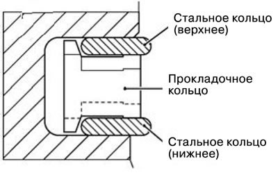
Note:
- The spacer ring and steel ring can be installed in both directions.
- The upper and lower steel rings are interchangeable parts.
2). Installing the steel ring. Insert one end of the steel ring into the piston groove first, then insert the rest of the ring by hand (See the picture).
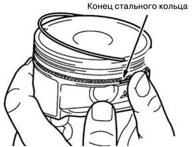
Note: Do not use a ring expander to avoid damaging the steel ring.
3). After installation is complete, the steel ring should rotate freely both clockwise and counterclockwise.
8. Install piston ring No. 2 (7).
9. Install piston ring No. 1 (6).
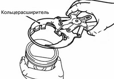
1). Use a ring expander to install the piston rings. The mark should face up (to the top of the piston) (See the picture).
2). Marks on piston rings: (See the picture).
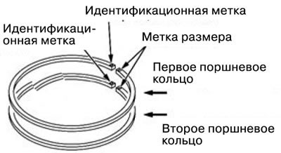
Meaning of labels:
- "1T": First piston ring.
- "2T": Second piston ring.
- Size markings:
| Size | Size marking |
| Standard | Absent |
| Increased 0.25 mm | 25 |
| Increased 0.50 mm | 50 |
10. Install the upper connecting rod bearing (5).
11. Install the piston and connecting rod assembly (4).
1). Lubricate the piston, piston ring and piston pin with engine oil.
2). Arrange the steel ring and piston ring connectors as shown in the figure.
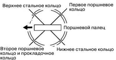
3). Insert the piston and connecting rod assembly into the cylinder from the top side so that the arrow on the top of the piston points toward the front of the engine (towards the timing belt drive).
4). Using a ring expander, compress the piston rings, then insert the piston with the connecting rod into the cylinder. Do not knock on the piston to avoid damage to the piston rings and connecting rod (See the picture).
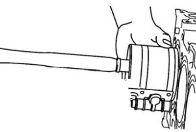
12. Install the lower connecting rod bearing (3).
13. Install the connecting rod cover (2).
1). Align the marks made during dismantling of the parts, then install the connecting rod big end cover. If a new connecting rod without markings is installed, position the bearing mounting groove on one side (See the picture).
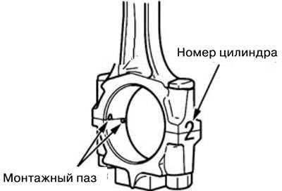
2) Measure the gap (See the picture).
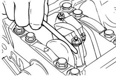
- Standard value: 0.10-0.25 mm.
- Maximum allowable value: 0.4 mm.
14. Install the connecting rod cap nut (1).
Note: If the work is carried out without dismantling the cylinder head, before installing the connecting rod nut, it is necessary to unscrew the spark plug of the corresponding cylinder.
1). Check the condition of the connecting rod bolt by screwing the nut manually along the entire length of the threaded surface of the bolt.
2). Lubricate the bottom and threaded surface of the nut with engine oil.
3). Tighten the nut by hand.
4). Then tighten the nuts sequentially with a wrench to the specified tightening torque - 27±2.0 N·m
5) Mark the top side of the nut with paint (See the picture).
6). Apply a paint mark on the bolt at an angular distance of 90°-94° clockwise from the mark on the nut (See the picture).
7). Tighten the nut until the marks on the bolt and nut align.
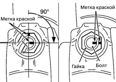
Note: If the nut is tightened less than 90°, the connecting rod cap will not be secured securely enough. If the nut is tightened more than 100°, loosen the nut and tighten it again.