



2. Remove the cap from the first connecting rod (as marked during disassembly). Remove the old bearing shells and wipe the bearing surfaces of the connecting rods and caps with a clean, lint-free cloth. They must be absolutely clean.
Checking the clearance of connecting rod bearings
3. Clean the back of the new upper bearing and insert it into the connecting rod. Make sure the tongue of the bearing fits into the groove in the connecting rod. Do not hammer the bearing into place or scratch the bearing surfaces. Do not lubricate the bearings at this stage.
4. Clean the back of the other half of the bearing and insert it into the connecting rod cap. Again, check that the tongue of the bearing fits into the groove of the cap and do not use any grease. It is especially important that the bearing and connecting rod surfaces are absolutely clean and free of grease during assembly.
5. Position the piston ring gaps at 90° intervals around the piston circumference (see illustration).
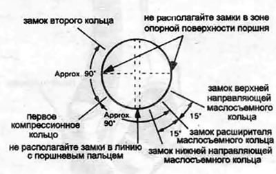
25.5. Adjust piston ring end clearances before installing pistons/connecting rods into the engine
6. Place a piece of rubber or plastic tubing over each connecting rod cap bolt.
7. Lubricate the piston and rings with clean engine oil and fit a piston ring compressor onto the piston. The piston skirt should extend approximately 6 mm to guide the piston into the cylinder. The rings should be fully compressed.
8. Turn the crankshaft so that the connecting rod journal of the first cylinder is set to the bottom dead center and lubricate the cylinder walls with engine oil.
9. With the arrow on the piston bottom (see illustration) facing the front of the engine (towards the timing belt), carefully insert the piston/connecting rod assembly into the number one cylinder so that the lower edge of the piston ring compressor rests on the cylinder block.
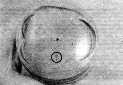
26.9. When installing the piston, the coil must face the toothed belt
10. Tap the top edge of the ring compressor to ensure a tight fit against the cylinder block all the way around.
11. Gently tap the top of the piston with the wooden handle of a hammer (see illustration), guiding the connecting rod onto the crankshaft journal. The piston rings have a tendency to pop out of the tool where they meet the cylinder, so press the tool down. Work slowly and stop immediately if you encounter any resistance as the piston enters the cylinder. Clear the obstruction before continuing. Do not force the piston into the cylinder - you may damage the rings and/or the piston.
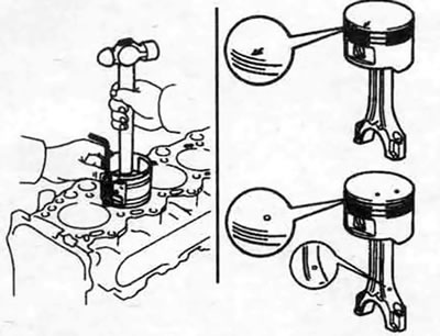
25.11 The piston can be inserted into the cylinder (carefully) with a wooden or plastic hammer handle
12. Immediately after installing the piston/connecting rod, check the clearance in the connecting rod bearings before finally screwing the caps.
13. Cut a piece of Plastigage tape to the appropriate size - slightly shorter than the width of the connecting rod bearing - and place it on the connecting rod journal of the first cylinder parallel to the axis of the journal (see illustration).
14. Clean the bearing surface of the connecting rod cap, remove the safety hoses from the connecting rod bolts and reinstall the cap. Make sure that the cap alignment mark is on the same side as the mark on the connecting rod.
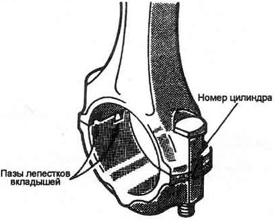
25.14. When installing the connecting rod bearing caps, align the cylinder number marks and the grooves of the bearing pads
Note: Make sure the mark on the crank is facing forward (towards the timing belt).
15. Install the nuts and tighten them to the required torque in three stages.
Note: Use a thin-walled socket head to avoid torque measurement error due to the socket head jamming between the cap and the nut. If the socket head jams between the nut and the cap, lift it slightly so that it does not touch the cap. Do not rotate the crankshaft during this operation.
16. Unscrew the nuts and remove the cover, being careful not to disturb the Plastigage tape.
17. Compare the width of the crushed Plastigage tape with the scale printed on the tape package and determine the gap size. Compare this value with the specification (provided in this chapter).
18. If the clearance is not within specification, the bearings may be the wrong size (use a different oversize bearing). Before deciding whether to use different bearings, make sure the bearings were free of oil or dirt when the clearance was measured. If the Plastigage is noticeably wider on one side than the other, the journal is tapered (see section 19).
Final installation of connecting rods
19. Carefully remove all traces of Plastigage from the main journals and/or bearing surfaces. Do not scratch the bearing surfaces - remove the tape with your fingernails or a wooden scraper.
20. Make sure the bearing surfaces are completely clean, then apply an even coat of clean molybdenum grease or engine assembly grease to both bearings. To lubricate the bearing in the connecting rod, you will have to push the piston into the cylinder - first fit the safety tubes onto the bolts.
21. Move the connecting rod back and install it on the journal, remove the safety tubes from the bolts, install the cover and tighten the nuts to the required torque. Tighten in three stages.
22. Repeat the entire procedure for the remaining pistons/connecting rods.
23. It is important to remember the following:
- a) During assembly, ensure that the reverse surface of the liners and the bearing surfaces of the connecting rods and caps are absolutely clean
- b) Check that the pistons/connecting rods match the cylinders you are installing them in.
- c) The arrow on the piston must point towards the front of the engine.
- d) Lubricate the cylinder walls with clean engine oil.
- d) Lubricate the bearing surfaces when installing the connecting rod caps after measuring the lubrication clearance.
24. After installing all pistons/connecting rods, turn the crankshaft by hand a few revolutions to check that it rotates smoothly.
25. As a final operation, it is necessary to check the axial clearance of the connecting rods. This procedure is described in section 13.
26. Compare the measured clearance with the specification. If the clearance was within the norm before disassembly and the old crankshaft and connecting rods were used during assembly, the clearance should still be within the norm. If a new crankshaft or new connecting rods were installed, the axial clearance may not correspond specifications. In this case, the connecting rods must be removed and taken to a car repair shop for grinding.