
2. Remove the cover of the first connecting rod.
Checking the lubrication clearance of the connecting rod bearings
3. Clean the new bearing and install it on the connecting rod. Do not lubricate the liner yet.
4. Clean the second earbud and install it in the cover.
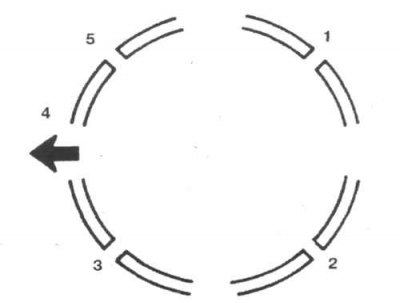
25.5 Rotate the piston rings as shown in the illustration before installing the pistons and connecting rods in the engine
1. Gap of the first compression ring; 2. Clearance of the upper oil scraper ring; 3. Gap of the second compression ring and expansion ring; 4. To the crankshaft pulley; 5. Clearance of the lower oil scraper ring
5. Rotate the piston rings so that their gaps are at 90°to each other (25.5).
6. Put pieces of a rubber hose on rod bolts.
7. Lubricate the pistons and rings with clean engine oil and install the piston ring compressor on the piston.
8. Turn the crankshaft so that the neck of the first cylinder is at bottom dead center, and lubricate the cylinder walls.
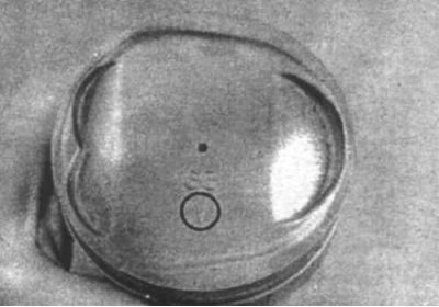
25.9 The mark on the piston head must point towards the timing belt
9. Check that the mark on top of the cylinder (25.9) pointing towards the timing belt, and install the piston and connecting rod into the cylinder so that the piston ring compressor contacts the surface of the cylinder block.
10. Check up, that the compressor of rings densely adjoined to a surface of the block of cylinders.
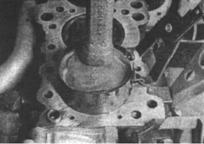
25.11 The piston can be lowered deep into the cylinder using a wooden handle
11. Tapping the piston with a hammer handle (25.11), lower the piston deep into the cylinder and install the connecting rod on the crankshaft journal.
12. Before final installation of the connecting rod cap, the bearing clearance must be checked.
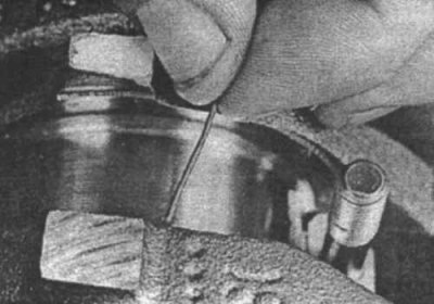
25.13 Lay strips of Plastigodge film on each of the crankpins, parallel to the axis of the crankshaft
13. Cut a piece of Plastigodge slightly shorter than the width of the connecting rod bearing and lay it on the connecting rod journal, parallel to the axis of the crankshaft (25.13).
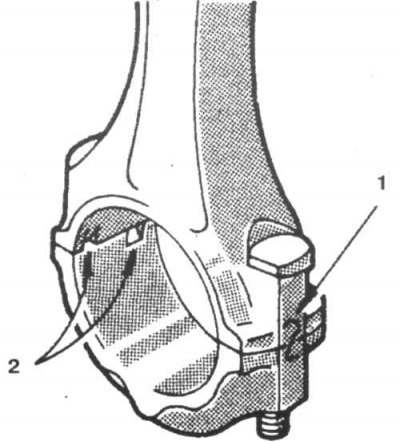
25.14 Align the numbers indicating the cylinder number and the tabs on the liner when installing the connecting rod caps
1. N cylinder; 2. Lugs and grooves
14. Clean the surface of the cover insert and install the cover on the connecting rod (25.14).
15. Install the nuts and tighten them to the correct torque in three steps.
16. Unscrew the nuts, and carefully remove the cover.
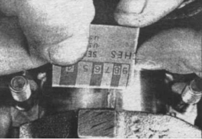
25.17 Measure the Plastigodge film width to determine the bearing lubrication gap
17. Compare the width of the crushed film with the special scale supplied with the film to check the lubrication gap (25.17).
18. If the clearance differs from the required value, install inserts of a different size. Check that there is no dirt or oil between the bearings and the connecting rod or cap. If the crushed film is wide at one end, the crankshaft journal is probably tapered.
Final installation of connecting rods
19. Remove traces of Plastigodge film.
20. Check that the surface of the liners, connecting rods and caps are perfectly clean, then lubricate the liners with an even layer of molybdenum grease.
21. Install the connecting rod on the neck, install the cover and tighten the fixing nuts to the required torque in three stages.
22. Install the remaining pistons and connecting rods in the same way.
23. After all the pistons and connecting rods are installed, turn the crankshaft a little by hand and check that nothing interferes with its rotation.
24. Check up an axial backlash of rods.